26
9 Flue Preparation and Installation
Diagram 9.13
13022
9.12 Top Horizontal Side flue - Standard
Part No. A2043400. Refer to diagram 9.8 for
kit contents.
9.13 Flue Length
Remove the top flue outlet cover secured with four screws,
see diagram 9.2.
Temporarily fit the flue elbow, measure the distance from the
outside wall to flue elbow. If the measurement ‘Y’ exceeds
652mm, then the appropriate length of extension pipe is
required. The minimum dimension for LH is 270 and RH 242
to suit a minimum wall thickness of 75mm, see diagram 9.11.
9.14 Flue Fitting
Remove the flue elbow.
Separate the flue duct from the terminal by twisting to release
the terminal catch, then pull out of the retaining seal, refer to
diagram 9.9.
The flue duct cutting length (L + 11mm.) is shown in diagram
9.9.
The air duct should be cut at the opposite end to the terminal
The plastic flue duct MUST be cut at the opposite end to the
terminal catch.
The plastic flue duct extensions MUST be cut at the opposite
end to seal.
The cut ducts must be de-burred and all filings and debris
removed.
Insert the flue duct into the air duct terminal assembly,
remembering to engage the catch within the terminal.
NOTE: If you require to lubricate the seals to ease installation,
do not use mineral oils or grease, silicon grease or water is
recommended.
Fit the sealing collar behind the locating lugs on the flue
terminal, see diagram 9.6.
Push the flue assembly into the wall, externally or internally,
initially until the end of the assembly protrudes a short way
from the inside face of the wall. This will enable the internal
trim ring (if required) to be positioned and allow the flue
assembly to be drawn back into the flue elbow.
Secure the flue elbow in position on top of the boiler with four
torque headed screws supplied.
Draw the flue assembly from wall and engage the flue duct
into the elbow and butt fit between the air duct and flue elbow.
Ensuring the correct alignment of the terminal.
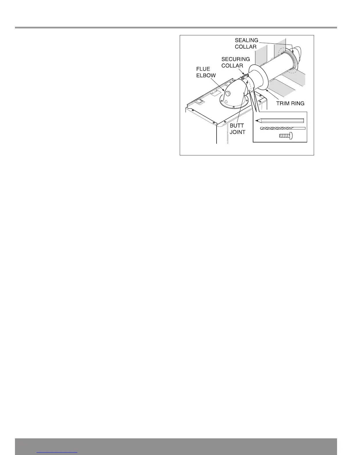
Fit the securing collar into position, mark through two of the
pre drilled holes in the securing collar. Remove securing
collar and drill two 3mm diameter holes one in the elbow and
one in the air duct, take care not to pierce the inner flue duct.
Fit the securing collar and secure with screws provided, see
diagram 9.13.
Slide the internal trim ring back against the wall, securing in
place with a small amount of sealant if required.
NOTE: If the air and flue ducts have been correctly cut to the
instructions the sealing collar should fit flush with the outside
wall, check this.

 Loading...


