12776
Diagram 12.4
12 Servicing
A competent person should only carry out any adjust-
ment to the gas valve, refer to diagram 12.4.
Monitor the combustion reading and at max rate the read-
ing should be 9.3% ± 0.5.
If adjustment proves necessary then proceed as follows:
Press the “reset” button on the controls fascia, release and
immediately press and hold in the “+” button. After approxi-
mately 5 seconds “Hi” will be displayed. Pressing the mode
button when “Hi” is selected will force the boiler to maximum
rate, the display will flash between “Hi” and the “default dis
-
play” this will indicate the boiler has been forced to maximum.
Adjust the maximum rate CO
2
with the throttle to 9.3%. (Ro-
tate anti-clockwise to increase).
To exit the check sequences press the “mode” and “+” buttons
simultaneously, this will reset the boiler to the default display.
Monitor the combustion reading and at min rate the read-
ing should be 9.3% ± 0.5.
If adjustment proves necessary then proceed as follows:
Press the “reset” button on the controls fascia, release and
immediately press and hold in the “+” button. After approxi
-
mately 5 seconds “Hi” will be displayed. Pressing the “+” or “-”
buttons will cycle between “Hi” and “Lo”. Pressing the mode
button when “Lo” is selected will force the boiler to minimum
rate, the display will flash between “Lo” and the “default dis
-
play” this will indicate the boiler has been forced to minimum.
Refer to diagram 12.4, remove the offset screw cover.
Adjustment of the CO
2
at minimum rate is very coarse so
carefully adjust the CO
2
with the offset adjustment to 9.3%.
(Rotate clockwise to increase).
Refit the offset cover and the cap on the test point.
To exit the check sequences press the “mode” and “+” buttons
simultaneously, this will reset the boiler to the default display.
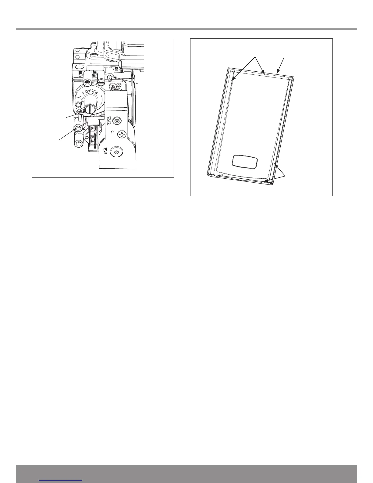
12.7 Casing panel seal check
Check the condition of the seal and replace if worn or dam-
aged.
To replace remove the old seal and thoroughly clean the
casing surfaces. Fit the new seals, these are supplied to the
correct lengths and are in four pieces, for use on the sides,
top and bottom, see diagram 12.5.

 Loading...


