48
221469B
4.16 Gas Valve - Honeywell
Before starting refer to Section 1.1.
Isolate the boiler from the electrical supply and close the gas
service cock, refer to Section 1.3.
Remove the outer case, refer to Section 1.4.
Remove the control housing, refer to Section 4.7 paragraph 7.
Remove the piezo unit bracket, see diagram 4.12.
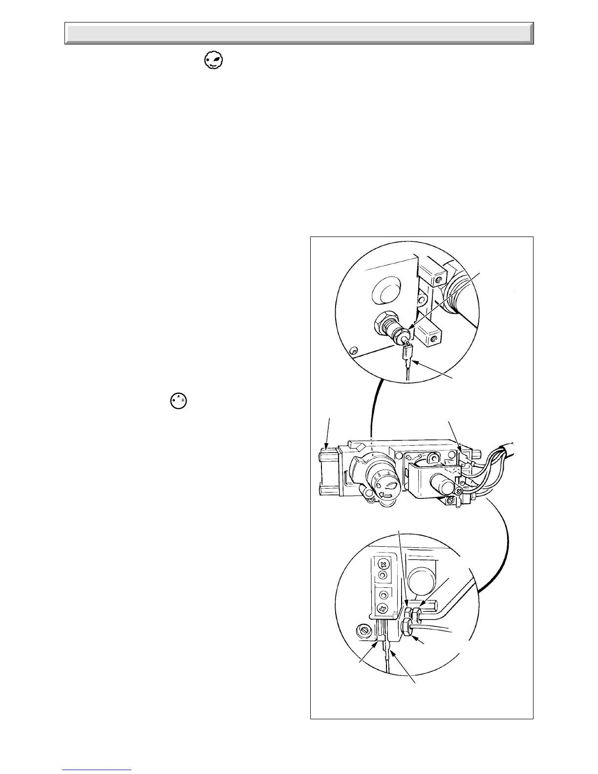
Disconnect the five electrical connectors, four at the front of the
gas valve and one at the rear, see diagram 4.11.
Disconnect the thermocouple at the gas valve.
Disconnect the pilot supply tube at the gas valve.
Remove the four extended hexagon screws at the right of the
valve.
Support the gas valve, disconnect the union nut of the gas
service cock and remove the valve complete with inlet pipe.
Separate the valve from the pipe, noting the fitted position.
Transfer the pilot tube adapter and the overheat cutoff connectors
to the replacement valve.
Discard the “O” rings and fit the new ones supplied, when fitting
the gas valve.
To connect the gas valve cables correctly, see diagram 4.10.
Light and adjust the boiler if necessary, refer to Commissioning
in the Installation Instructions. Adjust the pilot flame if necessary,
refer to Section 4.4, Pilot Burner.
Check and adjust the main burner pressure in the hot water and
central heating modes, refer to Commissioning in the Installation
Instructions.
4.16 Gas Valve - SIT
Before starting refer to Section 1.1.
Isolate the boiler from the electrical supply and close the gas
service cock, refer to Section 1.3.
Remove the outer case, refer to Section 1.4.
Remove the control housing, refer to Section 4.7, paragraph 7.
Remove the piezo bracket, see diagram 4.12.
Disconnect the four electrical connectors at the front of the gas
valve and the boiler overheat cutoff connectors, see diagram
4.11.
Disconnect the thermocouple at the gas valve.
Disconnect the pilot supply tube at the gas valve.
Remove the four extended hexagon screws at the right hand of
the gas valve.
Support the gas valve, disconnect the union nut of the gas
service cock and remove the valve complete with inlet pipe.
Separate the valve from the pipe. noting the fitted position.
Discard the “O” rings and fit the new ones supplied.
To connect the gas valve cables correctly, see diagram 4.10.
If necessary adjust the pilot flame, refer to Section 4.4.
Check and adjust the main burner gas pressure in both the hot
water and central heating mode, refer to Commissioning in the
Installation Instructions.
4 Replacement of Parts
HONEYWELL
Diagram 4.11
2276 S
OVERHEAT
CUT-OFF
CONNECTOR
ELECTRICAL
CONNECTOR
ELECTRICAL
CONNECTOR
OVERHEAT
CUT-OFF
CONNECTOR
PILOT TUBE
ADAPTOR
SECURING
SCREW
(4 + 4)
ELECTRICAL
CONNECTORS (4)
THERMOCOUPLE
NUT
PILOT TUBE
NUT
4.17 Central Heating Selector Switch
Before starting refer to Section 1.1
Isolate the boiler from the electrical supply and close the gas
service cock, refer to Section 1.3.
Remove the outer case, refer to Section 1.4.
Slacken the piezo bracket securing screws and remove the
bracket from the keyhole slots, see diagram 4.12. Take care
not to strain the piezo and electrical leads.
Pull the leads off from the switch, see diagram 4.12.
To remove the switch press the retaining tabs at the sides.
The polarity of the electrical connections is not important.
 Loading...


