49
221469B
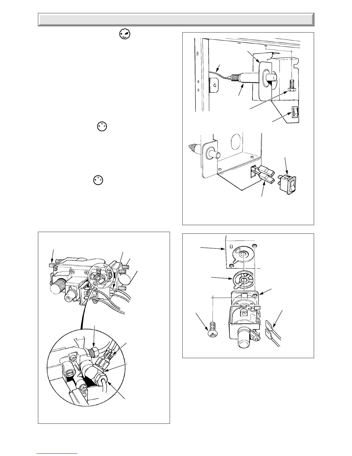
Diagram 4.11
SIT
Diagram 4.12
4 Replacement of Parts
2866 S
4451 S
SECURING
SCREW (4 + 4)
ELECTRICAL
CONNECTORS (4)
PILOT TUBE NUT
ELECTRICAL
CONNECTORS
OVERHEAT
CUT-OFF
CONNECTOR
THERMOCOUPLE
NUT
PIEZO UNIT BRACKET
IGNITION LEAD
ELECTRICAL
CONNECTORS
PIEZO UNIT
SELECTOR SWITCH
SECURING
SCREW (2)
SELECTOR
SWITCH
4.18 Modulator - Honeywell
Before starting refer to Section 1.1.
Isolate the boiler from the electrical supply and close the gas
service cock, refer to Section 1.3.
Remove the outer case, refer to Section 1.4.
Disconnect the two electrical connectors at the modulator, see
diagram 4.13.
Remove the modulator, secured with two screws.
Discard the gasket and fit the new one supplied, when fitting the
modulator.
Light, check and adjust the boiler if necessary, refer to
Commissioning in the Installation Instructions.
4.19 Modulator - SIT
Disconnect the two electrical connections at the modulator, see
diagram 4.13. Unscrew the centre shaft nut “A” and remove the
modulator coil.
Check and if necessary, adjust the boiler, refer to Commissioning
in the Installation Instructions.
The polarity of the electrical connections is not important.
4.19 Solenoid - SIT
Disconnect the two electrical connectors at the solenoid, see
diagram 4.13.
Remove the two solenoid securing screws and remove the
solenoid.
The polarity of the electrical connections is not important.
Diagram 4.13
HONEYWELL
2854 S
ELECTRICAL
CONNECTOR
(2)
MODULATOR
SCREW
(2)
GAS
VALVE
GASKET
 Loading...


