1 0991 497 EN - 24.03.2017
3010 ¾” VALVE MANUAL
INSTALLATION, USE AND MAINTENANCE
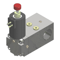
- Tighten the lock nut (3).
- The adjustment is finished.
3.9 PIPE RUPTURE VALVE (VC) TEST (IN THE VALVE BLOCK) – N° 5
WARNING
Before doing this test, the pipe rupture valve mounted on the piston should be adjusted (refer to VC
manual)
- Send the car with full load to the highest floor.
- Once the car has stopped.
- Loosen the lock nut (5) to test the rupture valve
- Completely tighten the screw n.5 .
- Call the car to the lowest floor.
- The test is finished.
NOTE:WHEN THE CAR DOWNWARD SPEED MATCHES THE INTERVENTION FLOW,THE
RUPTURE VALVE CLOSES TO STOP THE CAR (IN CASE OF BY-PASS RUPTURE VALVE,THE
CAR LOWERING CONTINUES SLOWLY).IN CASE THE RUPTURE VALVE DOES NOT
CLOSE,FOLLOW THE FACTORY INSTRUCTIONS TO REDUCE ITS INTERVENTION SPEED TO
BE ABLE TO RESTART THE TEST.
- Completely loosen the n.5 .
- During the standard car downward we do not have any intervention of the rupture valve
- Completely tighten the lock nut (5).
- The test is finished.
3.10 ADJUSTMENT OF THE MINIMUM RAM PRESSURE, VSMA (2:1 SYSTEMS) N° 6
Only in installations with traction 2:1.
- Close the ball valve (S).
- Press the manual lowering button (MM) to release pressure.
- Check the pressure on the manometer (MAN) is around 6 bar.
- If the pressure it not correct, adjust screw (6).
- The adjustment is finished.
3.11 MANUAL LOWERING OPERATION (EMERGENCY ONLY) – BUTTON (MM)
- Press the manual lowering button (MM) to send downward the car to the unlock door area
-
3.12 ADJUSTMENT OF THE MAXIMUM PRESSURE - HAND PUMP
- Close the ball valve (S).
- Verify that the suction tube is immersed in the oil.
- Loosen the screw (V) two or three turns to bleed the air.
- Push the lever several times till the oil starts flowing through the
screw (V).
- Tighten the screw (V) completely.
- Loosen the lock nut (10)
- Loosen the screw (10) two or three turns.
- Open the shut-off valve for pressure gauge exclusion (RUB).
- Push the hand pump lever to reach the maximum pressure,
adjust the screw (10) till the value is 2,3 times the full load
pressure (refer to the lift technical report).
-
Example:
If full load pressure is 35 bar, screw (10) should be adjusted to:
35 x 2,3 = 80,5
- When the pressure is correct.
- Tighten lock nut (10).
- Open the ball valve (S).
- The adjustment is finished.