1 0991 497 EN - 24.03.2017
3010 ¾” VALVE MANUAL
INSTALLATION, USE AND MAINTENANCE
2.7 HYDRAULIC CONNECTIONS
WARNING
Be care to keep clean the hose.Dirty inside may damage the piston and valve seal to affect the proper
system operating.
2.7.1 CONNECTION WITH HOSE
- Remove the end fitting of the ball valve, the nut and the locking ring.
- Make sure the terminal fitting is well secured to the shut-off valve.
- Clean and lubricate with oil the thread and the housing of the connector.
- Fix and tight the hose to the fitting.
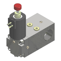
2.7.2 RIGID PIPE CONNECTION
- Cut the end of the tube at 90° (use a hack saw, DO NOT USE
A TUBE CUTTER).
- Lightly file (make smooth) the inside and outside edges of the
pipe.Pay attention to avoid any chips into the pipe.
- make sure that there is no dirty inside the pipe,as this may
cause a damage to the gaskets (seals) of the piston and the
valves jeopardising the correct functionality of the system.
- Remove the nut and the compression-fitting ring from the
silencer joint.
- Insert the compression fitting ring as shown in the figure.
- Make sure that the silencer joint is tight.
- Clean and apply a thin layer of oil to the thread and the joint
area.
- Insert the tube to the 24°cone.
- Turn the nut to completely tighten the compression-fitting ring.
- Use two wrenches and tighten the nut until the ring comes in
contact with the pipe and no more rotation is possible.
3 ADJUSTMENTS AND TESTS
See references on page 3
3.1 ADJUSTMENT OF THE MINIMUM PRESSURE UPWARD – N° 11
- Close the ball valve (S)
- Start the motor-pump (refer to the controller manual).
- Tighten screw (11) to get 5-6 bar pressure.
- Tighten the lock nut (11).
- Re-open the ball valve (S).
- The adjustment is finished.
3.2 ADJUSTMENT OF THE OVERPRESSURE – N° 1
- Open the shut-off valve of the manometer (RUB).
- Close the ball valve (S).
- Loosen the lock nut (1).