1 0991 497 EN - 24.03.2017
3010 ¾” VALVE MANUAL
INSTALLATION, USE AND MAINTENANCE
- Remove the spilled oil, remove the oil leaks, keeping equipment clean so leaks can be detected and
easily removed.
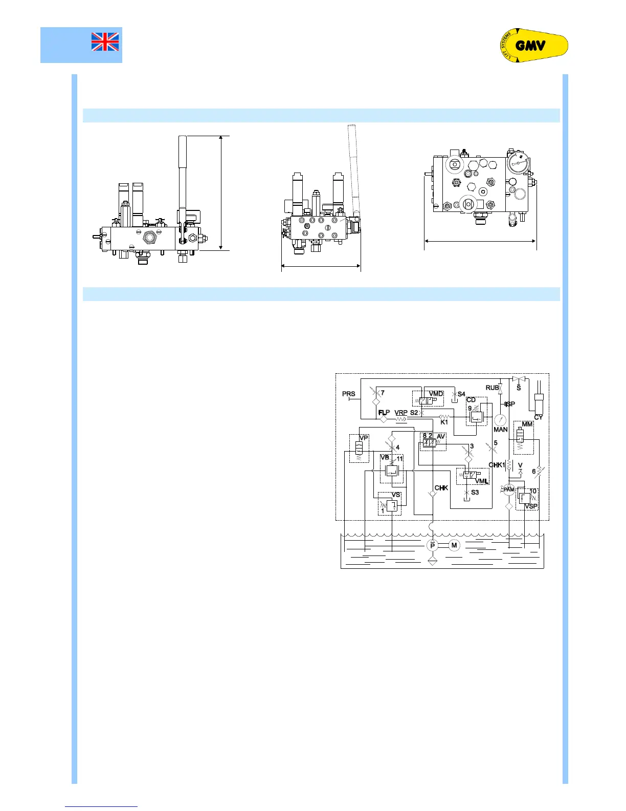
2.2 3010 ¾” VALVE DIMENSIONS
Pressure safety valve adjustment (p/max)
Levelling / slow speed adjustment (up/down)
Deceleration adjustment (up/down)
Screw for rupture valve test ( EN 81.20)
Minimum ram pressure adjustment
Downward start adjustment
Down speed compensator (empty/full load)
Hand pump max. pressure adjustment
Minimum upward pressure adjustment
Shut-off valve for pressure gauge exclusion
Hand pump air purge screw
Jump speed solenoid valve (upward/downward)
Fixed filer (don’t remove)
Inspection gauge fitting (EN 81.20)
Blocking screw (don’t remove)