EasyManuals Logo

GMV 3010 User Manual

GMV 3010
16 pages
To Next Page IconTo Next Page
To Previous Page IconTo Previous Page
Page #8 background imageLoading...
Page #8 background image
1 0991 497 EN - 24.03.2017
1.01
ENG
3010 ¾” VALVE MANUAL
INSTALLATION, USE AND MAINTENANCE
8 / 16
2.4 DECELERATION DISTANCES AND SIGNALS
CAR SPEED
V
N
[m/s]
DISTANCE C-E
UP [m]
DISTANCE G-I
DOWN [m]
0 < 0.15
0.10
0.15
0.10 < 0.15
0.15
0.20
0.16 < 0.30
0.20
0.30
2.5 ELECTRICAL CONNECTIONS
Electrical connections must be performed by qualified and experienced personnel.
Before doing any work is necessary to disconnect all electrical power by opening the main switch.
Power wires must be of sufficient section to support the required current and appropriate insulation for the
voltage of the mains.
Wires must not come in contact with hot parts.
The ground wire should always be connected to the screw marked with the appropriate symbol.
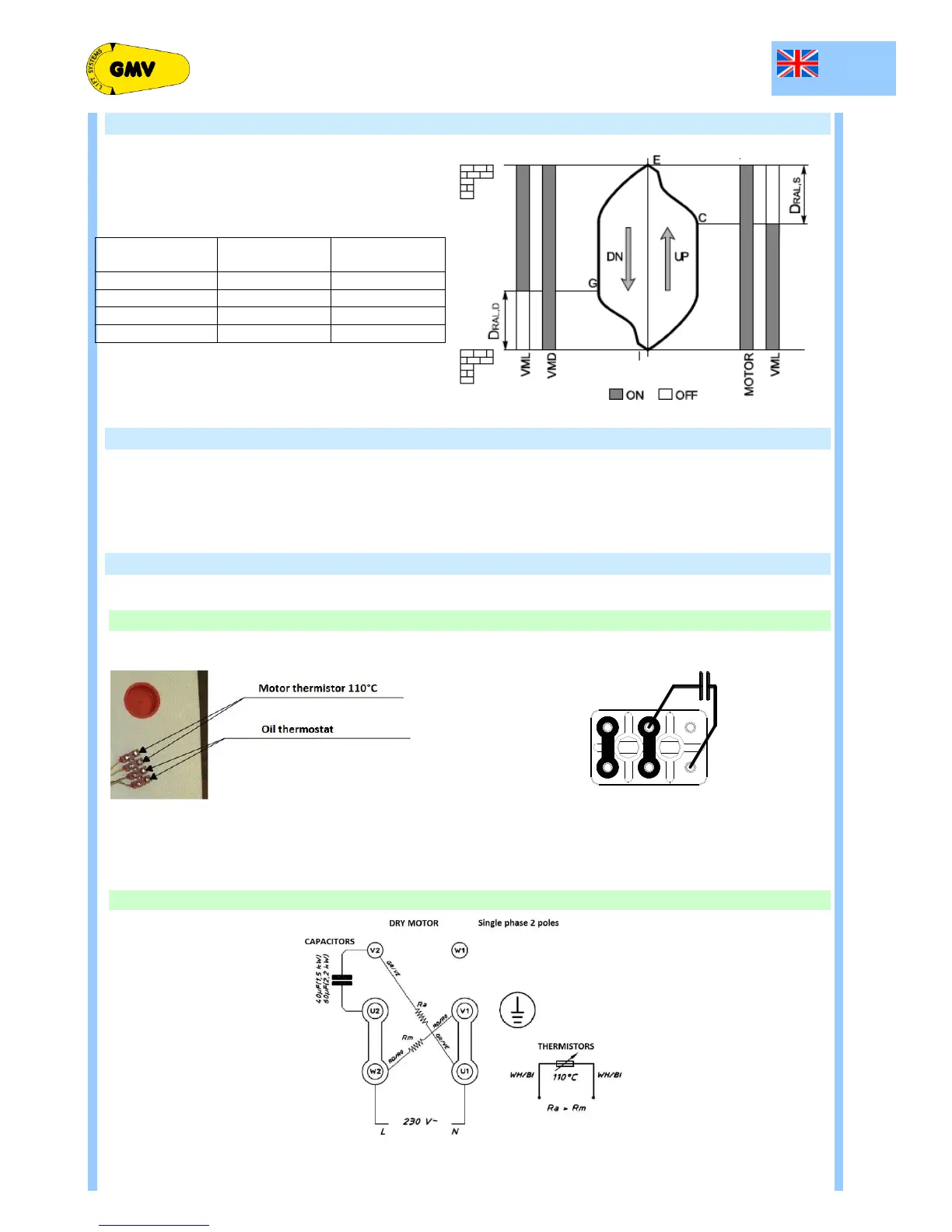
2.6 CONNECTION BOX
Power units with immersed motor have the motor connection box located next to valve block.
Power units with dry motor have the motor connection box located in the motor itself.
2.6.1 POWER UNITS WITH IMMERSED MOTOR
W2
U2
V2
U1 V1
W1
2.6.2 POWER UNITS WITH DRY MOTOR

Questions and Answers:

Question and Answer IconNeed help?

Do you have a question about the GMV 3010 and is the answer not in the manual?

GMV 3010 Specifications

General IconGeneral
BrandGMV
Model3010
CategoryControl Unit
LanguageEnglish

Related product manuals