Operating Instructions and Safety Precautions for the 2100LP
& 2100HP
Chargers
Safety
Only a trained person should operate this equipment. The input
and output voltages used with this equipment may be high enough
to endanger life, so insulated, shrouded
connectors must be fitted.
Please read this manual completely and convey instructions to all
personnel concerned. Keep the manual in a safe and convenient
place.
It is advisable to thoroughly read the information on battery safety
supplied with the battery, prior to charging.
Towards the end of charge, lead acid batteries give off hydrogen
gas, which is explosive if in sufficient concentration, therefore
avoid flames and sparks. Appropriate measures must be taken to
ensure adequate ventilation.
Incorrect use of a charger or maladjustment of its controls can
damage a battery. The equipment has been factory set and does
not require user adjustment.
This product has been designed, manufactured and certified to be
in conformance with European Safety and EMC
Directives. Testing
has ensured that the battery and charger combination conform as
a system for use in Light and Heavy Industrial environments for
each respective product variant. The following notes are for the
guidance of the person installing and using the product.
The charger must be isolated from the input supply and the
battery, before
any of the panels are removed.
It is strongly
recommended that a Safety Warning Notice is placed at the input
supply isolator, to warn against inadvertent reconnection of the
mains supply and the isolator is locked in the off position.
Installation
Installation must only be carried out by suitably qualified personnel
and in accordance with current local and national wiring
regulations.
The unit
should be positioned using lifting equipment, placed under
the base.
Battery leads should not be altered without prior consultation with
service personnel.
The charger should be sited in a cool, dry, well-ventilated location
away from corrosive fumes and humid atmospheres.
The charger must have a minimum clearance overhead of 200mm,
ensuring ventilation is not obstructed at the rear intake and the
front exhaust vents.
The charger is for inside use only.
Before installation, check that:
The charger has not sustained any transit damage.
The rating is suitable for the intended input supply and ‘lead
acid’ battery to be charged.
The connector polarity is correct and matches the
polarity of
the battery connector.
Input supply
A hand operated lockable
isolator should be used in the
installation, to enable the charger to be disconnected from the
supply, for maintenance or repair work. The charger does not
exhibit high in-rush current, therefore type B or C circuit breakers
can be used.
The circuit breakers rating should be based on the chargers
maximum input current, as stated
on the rating plate.
Careful consideration must be taken when connecting this charger
to a generator. The generator must be capable of at least four
times the input power requirements
of the charger, failure to do so
can
result in damage to the charger. The generator should have
load step immunity to prevent undershoot and
overshoot with
typical loads. Typically the generator control bandwidth should be
less than 7Hz with good gain and phase margins.
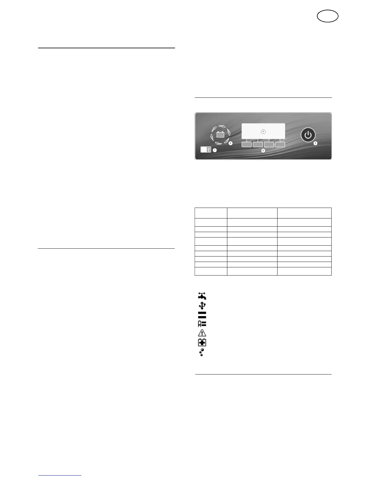
Display and Control
Overview
1.
Communications Port
2.
High Visibility -
Charge Status Indicator
3.
Softkeys
(The function of the button will be displayed on the LCD display)
4.
LCD Display
5.
Pause Button
Charge Status Indicator
INDICATION
CHARGE STATU S
INDICATION
MODE
1
Cycling red
Bulk charge / battery recovery
mode
2
Cycling yellow
Second stage / watering
3
All green
Charge complete
4
Green with cycling red
Auto-balance pulse / refresh
pulse / equalising / cool down
5
All flashing red
Critical
fault
6
All off
Standby / pause
/ inhibit
7
Left hand
indicator red
Power save mode
8
All flashing green
Watering alert
9
Flashing green with cycling
red
Watering alert & auto-balance
pulse
LCD Symbols
Watering system (Shown when enabled, flashing during operation)
Communications port (Shown when active)
Equalise (Shown when enabled, flashing during operation)
Automatic Equalise (Shown when enabled, flashing during operation)
Warning (Shown when a warning is active)
Battery Recovery Mode (Shown when enabled, flashing during operation)
*Air system enabled (Shown when enabled, flashing during operation)
Operation
Before connecting the battery, check that the battery voltage
corresponds to the voltage indicated inside the battery
symbol on
the LCD display.
The charger should be
permanently connected to the mains supply.
Standby
2
With the input supply connected and no battery, the charger will
enter the standby mode. During this mode the charge status
indicator will show indication 6
and the LCD display
will show
the
following:
GB