8
Fury X-3 Installaon and Operang Instrucons
Step 4. Connect 3-Phase DC Output Power Cables
Use an NEC-approved DC output cable (if not already equipped
from the factory) such as type UL 3311, UL 3279, or CSA CL 905 –
baery cable, with a polarized connector appropriate for baery
charging (such as REMA or Anderson Power Products Euro, SBX, or SB
connectors).
Use appropriate minimum wire size or larger for maximum kilowa
rang of charger – See Technical Specicaon Table (page 2): Min. DC
Output Wire Size (AWG).
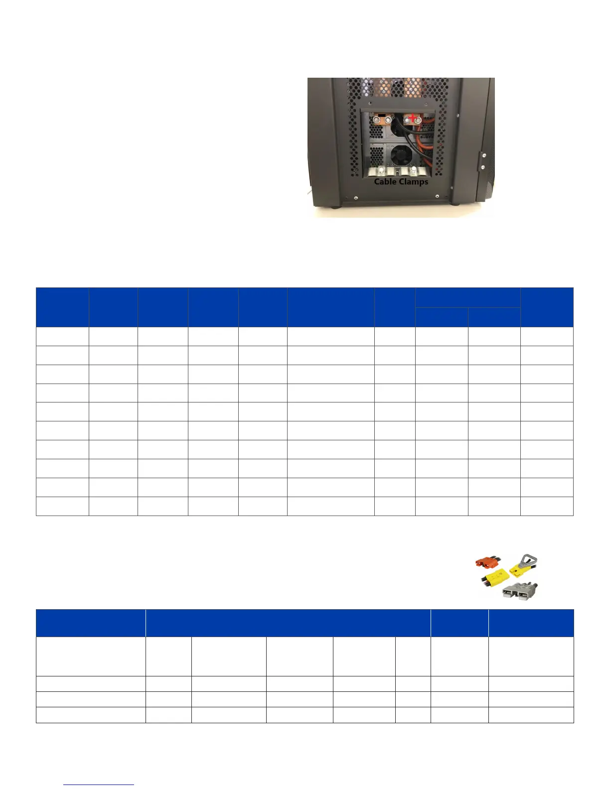
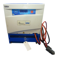
The panel located at the boom le of the charger must be used
for the DC power output cables. There are threaded studs for the
aachment of cable terminals which must be crimped or soldered
to the DC cable. The posive (red) cable is aached on the right and
the negave (black) cable is aached on the le. The clamps(s) at
boom are provided to secure the DC output cables.
Cobra Part
Number
Size
(AWG)
Stranding
Insulaon
Thickness
(mils)
Nominal
OD (in)
UL Style CSA
Amps
Cable
Weight
(lbs/MFT)
*
90ºC
**
105ºC
C9908B 8 133 x 29 0.060 0.29 UL 3311 & UL 3279 CL 905 83 92 84
C9906B 6 259 x 30 0.080 0.375 UL 3311 & UL 3279 CL 905 105 118 136
C9904B 4 420 x 30 0.080 0.43 UL 3311 & UL 3279 CL 905 140 157 189
C9902B 2 665 x 30 0.080 0.495 UL 3311 & UL 3279 CL 905 190 213 288
C9901B 1 836 x 30 0.095 0.565 UL 3311 & UL 3279 CL 905 220 246 348
C9910B 1/0 1064 x 30 0.095 0.615 UL 3311 & UL 3279 CL 905 260 291 444
C9920B 2/0 1330 x 30 0.095 0.664 UL 3311 & UL 3279 CL 905 300 336 551
C9930B 3/0 1672 x 30 0.095 0.719 UL 3311 & UL 3279 CL 905 350 392 663
C9940B 4/0 2109 x 30 0.095 0.785 UL 3311 & UL 3279 CL 905 405 454 820
C4925B 250 MCM 2451 x 30 0.095 0.806 UL 3311 only CL 905 455 510 970
Primary Posions
Signal
Posions
Connector
Aributes
Amps
(up to)
Wire Sizes
(AWG)
Wire Sizes
(mm
2
)
Quanty of
Posions
(up to)
Wire
Quanty of
Posions
(up to)
Touch Safe
SBE® 80 / SBO® 60 80 4 to 6 16 to 25 2 yes 8 yes
SBE®160 / SBX®175 175 10 to 1/0 5.3 to 53.5 2 yes 8 yes
SBE® 320 / SBX® 350 350 1/0 to 300 mcm 53.5 to 152 2 yes 8 yes
Example Polarized Connector: Anderson Power Products Baery Charging Connectors
Selecon Guide
Example Cable: Cobra Brand Baery Cable Chart
*Allowable Ampacies of Single Insulated Conductors, per NEC table 310-17 Cable manufactured in accordance with Federal EPA Rule, Title 40-part 82, (ODC’s)
**The 105°C cable ampacies are adapted from ICEA P-54-440/NEMA WC51- 1986(R1991). The ampacies are provided for informaonal purposes only. Acceptance of these values by any
governing authority is the responsibility of the end user. Ampacies are based on a single conductor, in free air, at 30°C ambient air temperature.
NOTE: Many of the mm² wire sizes are based on calculaons. See the catalog for specic mm² wire sizes.


 To Next Page