1818 1919
8. Installation
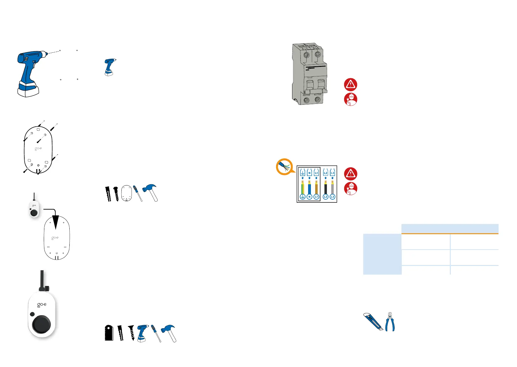
4.
Hook the go-e Charger into the wall bracket.
Optional: If required, attach the supplied U-piece di-
rectly above the charger, making it impossible to re-
move the device from the wall bracket. In addition, a
padlock (not included in the scope of delivery) can be
attached.
8. Installation
5.
The go-e Charger is equipped with an integrated DC
protection module with DC detection and additional
AC detection (6 mA DC, 20 mA AC).
On the building side, an RCD type A must be instal-
led and a miniature circuit breaker must be installed
upstream. The local installation regulations must be
observed.
Miniature circuit breakers with characteristic B or C
for 16 or 32 amperes are permissible:
• 3- or 4-pole for three-phase connection
• 2-pole for single-phase connection
2.
Drill holes at the four marked positions.
4x
3.
Attach the wall bracket with four screws and dowels
each. Drive the dowels into the wall with a hammer.
Make sure that the surface is not warped. The device
may not be attached if the wall bracket is distorted.
Compensate possible unevenness of the wall with
spacers (not included in the scope of delivery).
6.
The go-e Charger Gemini (2.0) may be connected
single-phase and three-phase. If necessary, lay an ad-
ditional supply line. When selecting the cable cross-
section, observe the simultaneity factor and the type
of installation. We recommend the following cable
cross-sections, but the electrician has to decide ac-
cording to local conditions:
11 kW 22 kW
as surface-
mounted
at least 2.5 mm² at least 6 mm²
in wall
at least 4 mm² at least 6-10
mm²
in insulation at least 10 mm² at least 10 mm²
The connection cable of the go-e Charger Gemini
(2.0) may also be shortened. Connection via a junc-
tion box is possible.
4X
Installation and operating manual go-e Charger Gemini / go-e Charger Gemini 2.0 | V 1.0Installation and operating manual go-e Charger Gemini / go-e Charger Gemini 2.0 | V 1.0