2020 2121
10a. Commissioning/operation on the device
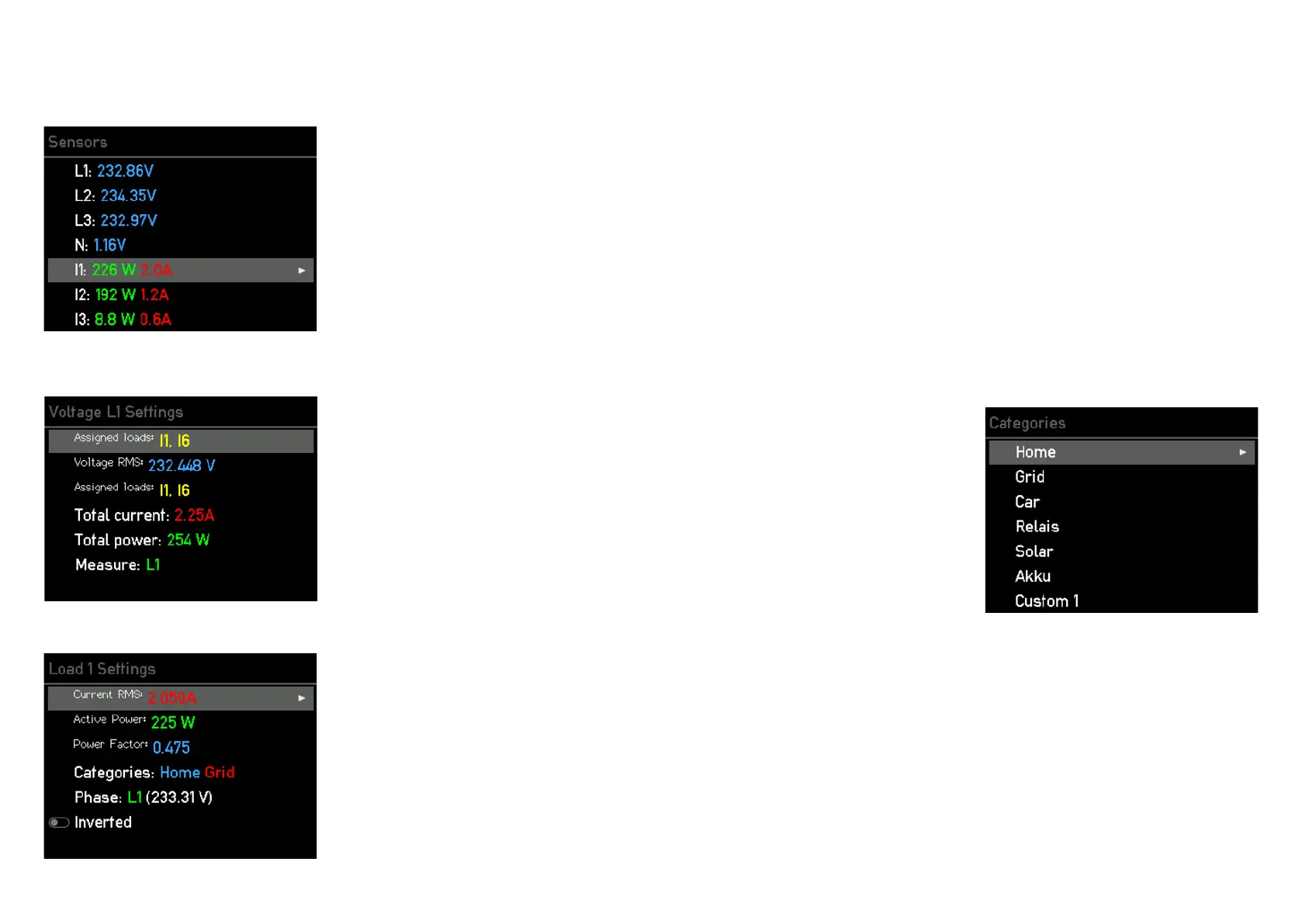
8. Sensors / Load settings
If you select one of the loads (I1 to I6) on the
"Sensors" page, you will get to the "Load set-
tings" overview.
Here you can use the slider to invert a load if
you have not connected a current transformer
with the arrows in the direction of the current.
In order for the power calculation to be correct,
the phase must be set correctly. Imagine that
the sensor measures 2 amps on your mains
6. Sensors
7. Sensors / Voltage settings
Under "Sensors" you can read the voltages,
currents and power in real time. L1 to L3
show the voltage of the phases connected
to the connecting clamp. I1 to I6 show the
values of the connected sensors (current
transformers). I corresponds here to the de-
signation Internal, which corresponds to
the connected sensor or also means load.
If you select L1, L2, L3 or N, you get to the volta-
ge settings of the phase.
Here you can see all the measured values of the
selected phase as well as the assigned loads
(internal/arom sensors). Just check whether the
voltage is approximately correct. If the current
and total power are not yet correct, this is not a
problem, because this conguration will be ex-
plained a little later.
Press the < button to return to the "Sensors"
overview.
connection, but without a voltage reference
we do not know whether we are feeding power
into the mains or drawing power from it.
Note that the power should always be positive
when drawing from the grid. With a solar in-
verter or an AC battery, the power should be
positive in feed-in operation, but if the batte-
ry is charged or the inverter has more standby
consumption than generation, the power may
be negative. If no power is being consumed, the
power should be close to zero.
It is very important that the correct phase
is set as the voltage reference. To nd out
which phase you have connected the sensor to,
trace the cables in the switch cabinet. Alterna-
tively, you can use a multimeter to check whet-
her the voltage at the go-e Controller matches
the fuse of the load.
The power factor can be between minus one
and plus one. Minus one means maximum
feed-in or charging for a battery without reac-
tive power, plus one means maximum draw or
production of energy. If the power is particular-
ly low, the power factor is not very meaningful.
For a pure ohmic load, the power factor should
be close to one.
To check the voltage allocation, you can sim-
ply switch on a large consumer with heating
elements in your household, e.g. a fan hea-
ter, a hairdryer or the electric cooker. If your
electric cooker is connected to a three-phase
system, checking is especially easy because
all phases are directly loaded with a power
factor of almost one. If the power factors are
incorrect and, for example, only plus or minus
9. Sensors / Load settings / Load
categories
After you have selected the "Categories" line in
the "Load settings" menu with the > key, you
will reach this submenu.
The go-e Controller does not know which sen-
sor you have mounted where. You set this with
the respective category.
s
There is the category Grid. This category is the
most important, because go-e Charger and go-e
Controller try to regulate it as much as possible
to zero during PV surplus charging.
one third or two thirds, you must adjust
the assignment. As long as the allocation
is not correct, your Controller cannot dis-
tinguish between feed-in and mains supply
and the PV surplus regulation will not work.
This submenu can also be used to dene the
load categories by navigating to "Categories"
and conrming with >.
 Loading...