1414 1515
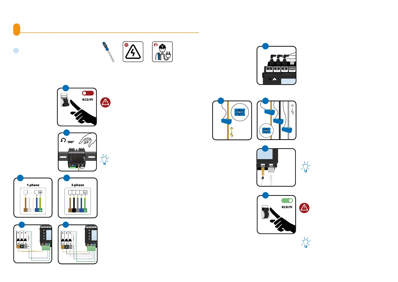
8. Installation
Required tools
a
Screwdriver
a
6.
*If it is not possible to install the current sen-
sors with the arrow pointing in the specied
direction for space reasons, the sensors can
also be inverted via the Controller menu or
the app.
Now connect the WiFi antenna and/or the
Ethernet cable to the Controller.
For optimal reception, lead the at cable of
the WiFi antenna out of the installation distri-
butor to attach the top there.
7.
You do not want to connect any further sen-
sors? (This is not necessary for the PV surplus
optimisation.) Then restore the voltage sup-
ply. Next, follow the instructions from point 5
in chapter 9 Installation (additional sensors).
8.
For PV surplus optimisation, we need enough
sensors to measure the power from or to the
grid. For three-phase connection, plug the jack
plugs of three current transformers into the
designated inputs for current measurement.
For example, in sensors one to three. For sin-
gle-phase connection, use only one current
transformer. The easiest way to do this is to
measure directly at the mains connection.
Attach one current transformer per phase.
The two arrows on the current transformer
must point in the direction of the current.
When connecting to the power grid, which we
call the " grid", the arrow should point from
the power grid towards the house.*
Please note: A maximum of one current
transformer may be attached to one pha-
se.
5.
6.
L2
Ensure that the circuit is de-energised by ob-
serving the ve electrical safety rules.
1.
Connect the Controller single-phase or three-
phase depending on the power connection.
If necessary, lay additional supply line. Insert
the conductors into the connecting clamp and
x it with a screwdriver. Also connect the neu-
tral conductor and the protective earth.
3.
Mount the go-e Controller on the DIN rail. We
recommend mounting according to the illus-
tration. However, the Controller can also be
mounted rotated by 180°.
Please note: The display can be rotated ac-
cordingly under the menu item "settings/de-
vice/rotate display".
2.
OFF
1
Optional
2
1-phasig
N
N
L1
L1
2
3
4
4.
The go-e Controller can also be connected to
a fuse of another consumer, for example the
electric oven. If this is not possible, you need
to install a new fuse.
L1
L1
L2
L3
5
6
6
L2
3-phasig
N
N
L1
L1
L2
L3
L2
L3
3
4
Connect
A / B / A+B
A B
7
ON
8