Topic Issue Possible Cause How to Tell Remedy
Problems
with the
Current
Current reading
shows 0A at
daytime, with
clear sunny
skies
Current is being limited
below 1A as per normal
operation or poor
connection between
solar array and
controller.
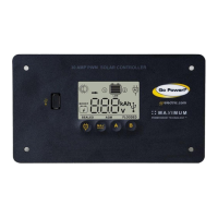
1. The State of Charge (SOC)
screen is close to 100% and
the Sun and Battery icon
are present with an arrow
between.
2. With the solar array in
sunlight, check voltage at
the controller solar array
terminals with a voltmeter.
3. If there is no reading at
the controller solar array
terminals, the problem is
somewhere in the wiring
from the solar array to the
controller.
Hold down the MAX BOOST
Button for approximately 3
seconds to activate Maximum
Power Boost.
This will allow the controller
to charge batteries to 14.4
+/-0.1V(oodedandAGM)
or 14.1 +/- 0.1V (Sealed/Gel)
with all current the solar array
is producing.
Check all connections from
the controller to the array
including checking for correct
wire polarity. Check that all
connections are clean, tight
and secure. Continue with the
solutions below for additional
help on low current readings.
Current reading
is less than
expected at
daytime, with
clear sunny
skies
1. Current is being
limited below 1A
as per normal
operation.
2. Incorrect series/
parallelconguration
and/or wiring
connections and/or
wire gauge.
3. Dirty or shaded
module or lack of
sun.
4. Blown diode in solar
module when two
or more modules
are connected in
parallel.
1. Battery State of Charge
screen is close to 100% and
the Sun and Battery icon
are present with an arrow in
between.
2. Check that the modules and
batteriesarecongured
correctly. Check all wiring
connections.
3. Modules look dirty, overhead
object is shading modules or
it is an overcast day in which
a shadow cannot be cast.
4. Disconnect array wires from
the controller. Take a voltage
reading between the positive
and negative array wire. A
12-volt array should have an
open circuit voltage between
17 and 22 volts.
Reconnect in correct
conguration.Tightenall
connections. Check wire
gauge and length of wire run.
Refer to Suggested Minimum
Wire Guage in Section 5.
If dirty or obstructed, clean
modules, clear obstruction or
wait for conditions to clear.
If the open circuit voltage
of a non-connected 12-volt
array is lower than the
manufacturer’sspecications,
the module may be faulty.
Contact the Go Power!
Technical Support team as
listed in section 13.1 for
assistance.
Problems
with
Inverter
Inverter
won’t turn
on
Inverter connected to
a battery which doesn’t
have ground connected
to the controller.
1. The inverter icon is
displayed on the
controller
Inverter battery ground
must be connected to the
ground of one of the batteries
connected to the charge
controller.
page 20
 Loading...