Wiring Diagram
the controller for proper operation. Do not connect the negative solar array or negative
battery controller wiring to the chassis of the vehicle.
5.
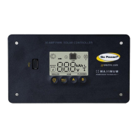
Mounting the GP-PWM-30. Mount the GP-PWM-30 to the wall using the included
four mounting screws.
IMPORTANT: You must set the battery type on the GP-PWM-30 before you begin
to use the controller. The default battery setting is for AGM batteries.
Congratulations, your GP-PWM-30 should now be operational. If the battery power
is low and the solar array is producing power, your battery should begin to charge.
6.
Re-torque: After 30 days of operation, re-torque all terminal screws to ensure the
wires are properly secured to the controller.
The GP-PWM-30 is based on a 30 amp max input from the solar modules. E.G. Three
modules in parallel with an input of 7 amps each equal a total input of 21 amps. Most
solarmoduleslisttheinputampsontheirspecicationslabel.
6.1 Charging Only One Battery
Use the following wiring diagram if you are using the GP-PWM-30 to charge only one
battery. First, connect your battery to the battery 1 terminals on the solar controller.
Then, connect the solar panel to the controller.
The controller will not work unless there is a battery connected to the
Battery 1 terminals.
Note
Note: Use a 30A fuse
or breaker
Wiring Diagram
page 8
 Loading...