Installation Instructions
Wire type is recommended to be a stranded copper UV resistant wire. Wire fatigue
and the likelihood of a loose connection are greatly reduced in stranded wire com-
pared to solid wire. Wire gauge should be able to sustain rated current as well as
minimizing voltage drop.
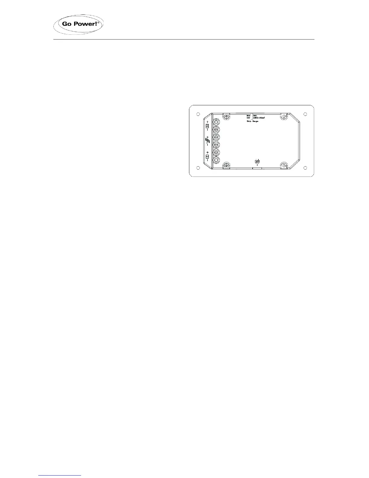
Wire Strip Gauge
Youwillndastripgaugediagramonthe
back of the GP-PWM-30, which helps
you to strip your wires to the correct
length. Insert wire into the concave slot
of the strip gauge until it meets the back
of the strip gauge slot. Mark the length
of wire from the back of the strip gauge
slot to the edge of the controller with a
penoryourngerandstripallwirestobe
connected to the controller to this length.
Suggested Minimum Wire Gauge
(Cable length 25 ft. max. from solar array to battery bank)
50 Watt Solar Module
80 Watt Solar Module
95 Watt Solar Module
110 Watt Solar Module
125 Watt Solar Module
160 Watt Solar Module
240 Watt Solar Module
Terminal Screw Torque
#14 Wire Gauge
#12 Wire Gauge
#10 Wire Gauge
#10 Wire Gauge
#10 Wire Gauge
#10 Wire Gauge
#10 Wire Gauge
16 inch pounds (1.8N.m)
IMPORTANT: Identify the polarity (positive and negative) on the cable used for the
battery and solar module. Use colored wires or mark the wire ends with tags. Although
the GP-PWM-30 is protected, a reverse polarity contact may damage the unit.
Wiring the GP-PWM-30. Wire the GP-PWM-30 according to the wiring schematic
in Section 6. Run wires from the solar array and the batteries to the location of the
GP-PWM-30. Keep the solar array covered with an opaque material until all wiring is
completed.
4.
Torque all terminal screws to 16 inch pounds (1.8N.m). Connect the battery wiring
tothecontrollerrstandthenconnectthebatterywiringtothebattery.
IMPORTANT: Always use 30A fuse circuit protection on the positive conductor
attached to a battery.
With battery power attached, the controller should power up and display information.
Connect the solar wiring to the controller and remove the opaque material from the
solar array. The negative solar array and battery wiring must be connected directly to
page 7
 Loading...