Operating Instructions
8.3 Viewing the Controller
Display Information
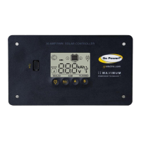
The GP-PWM-30 has two modes to
watch the display information, manual
and auto scroll.You can change between
the two modes by holding down the
A Button for 3 seconds.
Mode 1- Manually Scroll Through
Display Information
Battery 1 Status Values
To toggle between Battery Voltage, PV
Charging Current and Battery State
of Charge (SOC) for Battery 1 and 2,
press the B Button.
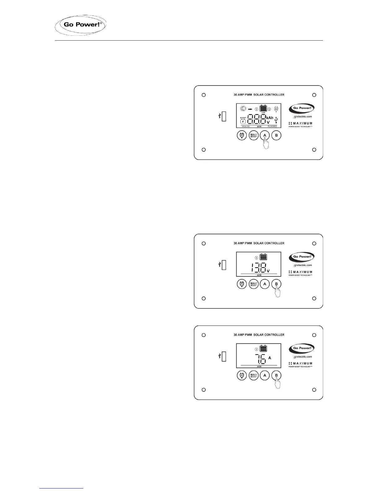
Battery 1 Voltage Screen
Push the B Button to show the
voltage for Battery 1.
Icons Displayed: Battery SOC,
Volt Symbol (V), Symbol 1
Battery 1 Current Screen
Push the B Button to show the PV
charging current for battery 1. The
GP-PWM-30 will begin to limit the
current as Battery 1 reaches a full
charge. The current that is not used for
Battery 1, is used to charge Battery 2.
Icons Displayed: Arrow, Ampere
Symbol (A), Battery SOC, Symbol 1
page 13
 Loading...