WIRING DIAGRAMS:
One apartment with 16 PENTHA monitors, 4 DP-GB2A distributors and Golmar DC lock release.
13
Configure the end of line in
the last monitor.
DIP 6 to ON.
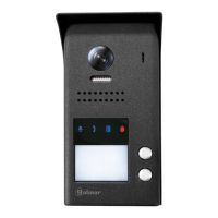
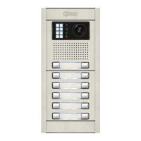
Access panel
**
Lock release
max
. 12 Vdc/270mA.
BUS
BUS
BUS
BUS
BUS
BUS
BUS BUS
D
C
B
A
DP-GB2A
BUS
BUS
End of line
ON
End of line
OFF
CODE 3 CODE 2
CODE 1
CODE 13
CODE 12
**
**
** **
**
CODE 0
**
Configure the end of line in
the last distributor.
Switch to ON.
*
*
AP
Distances and cross-sections:
DP-GB2A
A
C
B
C
Important: For AC lock releases or a second lock release, see diagram 'Connection of Golmar AC and DC lock releases' on p. 18.
(1)
(1)
NA2
+
AP-
C1
NA1
AP+
C2
AP+ AP-
P1 P2
BUSBUS
Relay 2
Relay 1
_
12Vdc
ON
1 2 3 4 5 6
SW1
(1)
BUS
BUS
BUS BUS
D
C
B
A
DP-GB2A
D
Twisted pair 2x0.75mm
2
Twisted pair 2x1mm
2
60m
A
60m
B
30m
C
80m 80m 40m
Cable
10m
D
15m
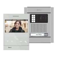
STAINLESS STEEL NEXA MODULAR GB2 VIDEO DOOR ENTRY SYSTEM KIT – HOUSES
FA- 2GB /A
N L
CN
Mains
100~240Vac
BUS (M) BUS(PL)
FA- 2GB /A
L
BUS
BUS
CODE 15 CODE 14
** **
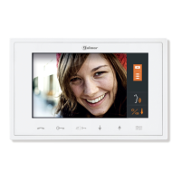
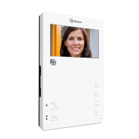
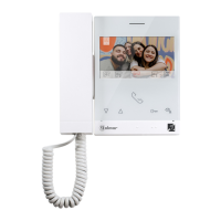
PENTHA
PENTHA
PENTHA
PENTHA
PENTHA
PENTHA
PENTHA
PENTHA
PENTHA PENTHA