Commander III
2-27
that depressing the OK button will stop the machine.
If the cursor is moved from one of these positions
(for example to the F or R button), always move it
back when nished . Cycle the controller power to
deactivate the "Sim Mode".
069G+
Switch Test 2
▼▲
069G+
0.22v0.22v
Switch Test 2 shows the status of various switches
and electrical controls. The emergency stop icons will
indicate red when the corresponding switch is pressed.
The variable speed dial should range from 0.21 to
5.00 volts. The FNR and reset switch indicators will
turn green when the corresponding switch is pressed.
Switch Test 3 shows the status of the remaining
variable speed dial and FNR switch controls.
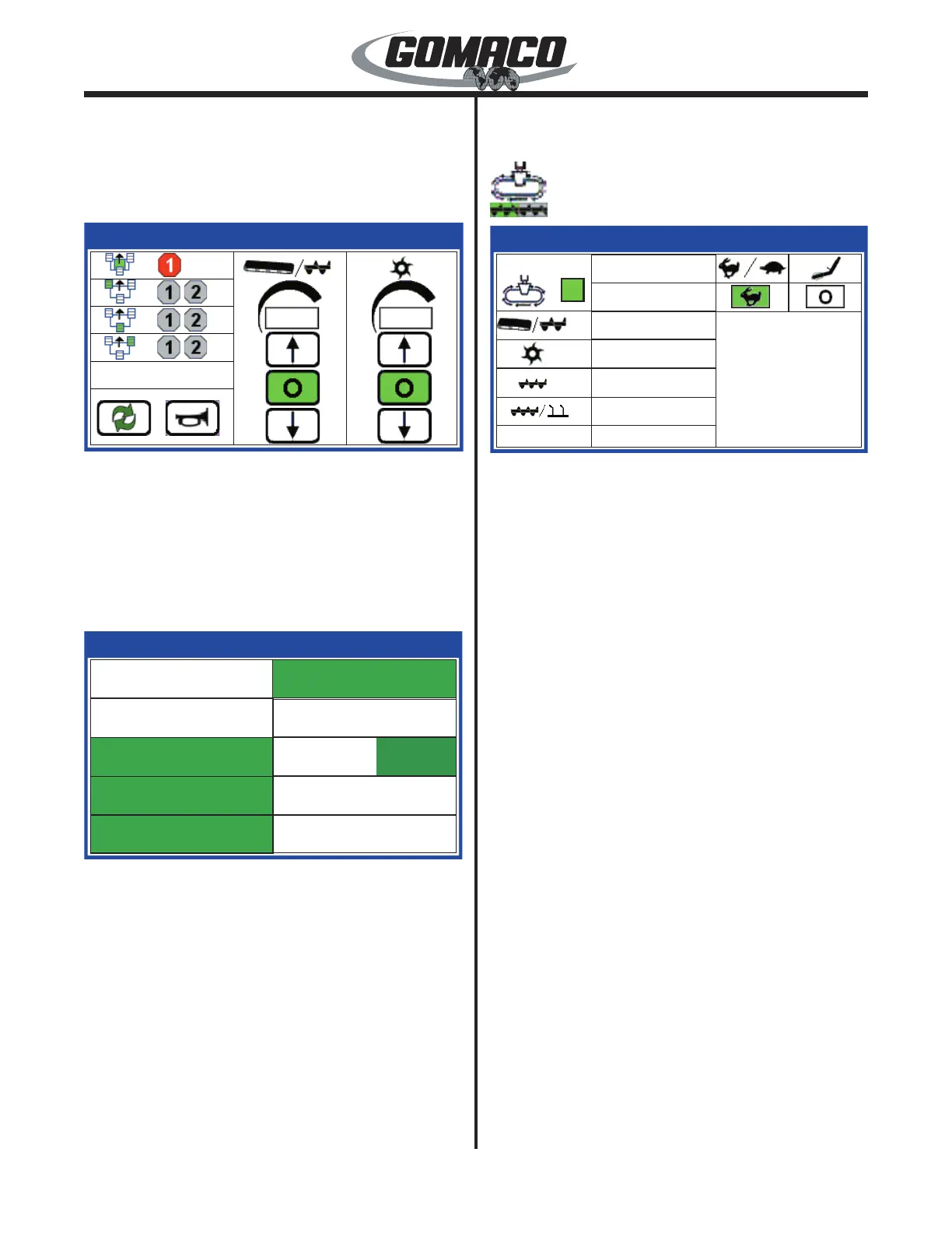
163G+
Output Status 1
Backup Alarm
Travel 2-Speed
Lift Dump
Travel Dump
Conveyor Dump
Trimmer Dump
Vibrator
1 2
Slope Stabilizer
Radius Assist
Track Brake
163G+
▲
Monitors the operating status of various output drive
signals. The indicators will turn green when the circuit
is energized.
Test Menu:
Travel display
031
252G+
Travel
Drive
55%
0%
0%
8.72v
6.80v
6.80v
252G+
F
0%
6.80v
0%
6.80v
Monitors the output drive percentage and voltage to
the control valve solenoids for the indicated icons in
the left column. A direction indicator for the track drive
is shown in the top left box. The output drive signal
will range from 0 to 100 percent in forward or reverse
directions. The control valve output voltage for the
travel and auger/conveyor will increase or decrease
from a center reading of approximately 6.80 volts. The
voltage will vary from 6.80 to 10.30 volts in the forward
direction and from 6.80 to 3.30 volts in the reverse
direction.
Note: The output drive center voltages may vary
according to uctuations in battery voltage supply.
The trimmer output drive drive signal will range from
0 to 100 percent in forward or reverse directions. The
voltage will vary from 6.80 to 10.30 volts in the forward
direction and from 6.80 to 3.30 volts in the reverse
direction.
The status of the track two speed switch and the off/
auto vibrator switch are also monitored.
 Loading...