Commander III
2-39
above the selection box is the slope percentage from
the sensor in the corresponding direction. Press the
odd number button in the data box to select cross
slope and the even number button to select long slope.
The exact procedure for setting the slope sensor
null (level) voltages is described in the Maintenance
chapter.
A green light next to the machine icon indicates that
the slope sensor is communicating with the control
system. If the light changes to white, the sensor is not
communicating with the control system.
Note: A 4-track paving conguration is equipped
with two dual axis (cross / long slope) sensors.
257G+
Slope Setup
Slope Transition
Slope Compensation
Steer Offset
Elevation Offset
12
12
257G+
▲
in
in
Note: A software update may be required if this
screen is not available on early G+ machine
models.
Used to turn the slope compensation and transition
system on or off. Press the number button indicated
in a data box to select a parameter to change. Press
the up (▲) or down (▼) navigation buttons to select a
green check mark or to change the data value. Enter
the correct value for the elevation and steer stringline
offset distance to use the slope compensation system.
For more information on setup and operation of
the slope compensation/transition system, refer to
Operating Instructions for the Automatic Grade/
Slope Transition System.
Setup menu
Sensor setup
220-0044
117G+
Sensor Setup
Bump Filter
Steer
Bump Filter
Sensitivity Sensitivity
Elevation
55
117G+
▼
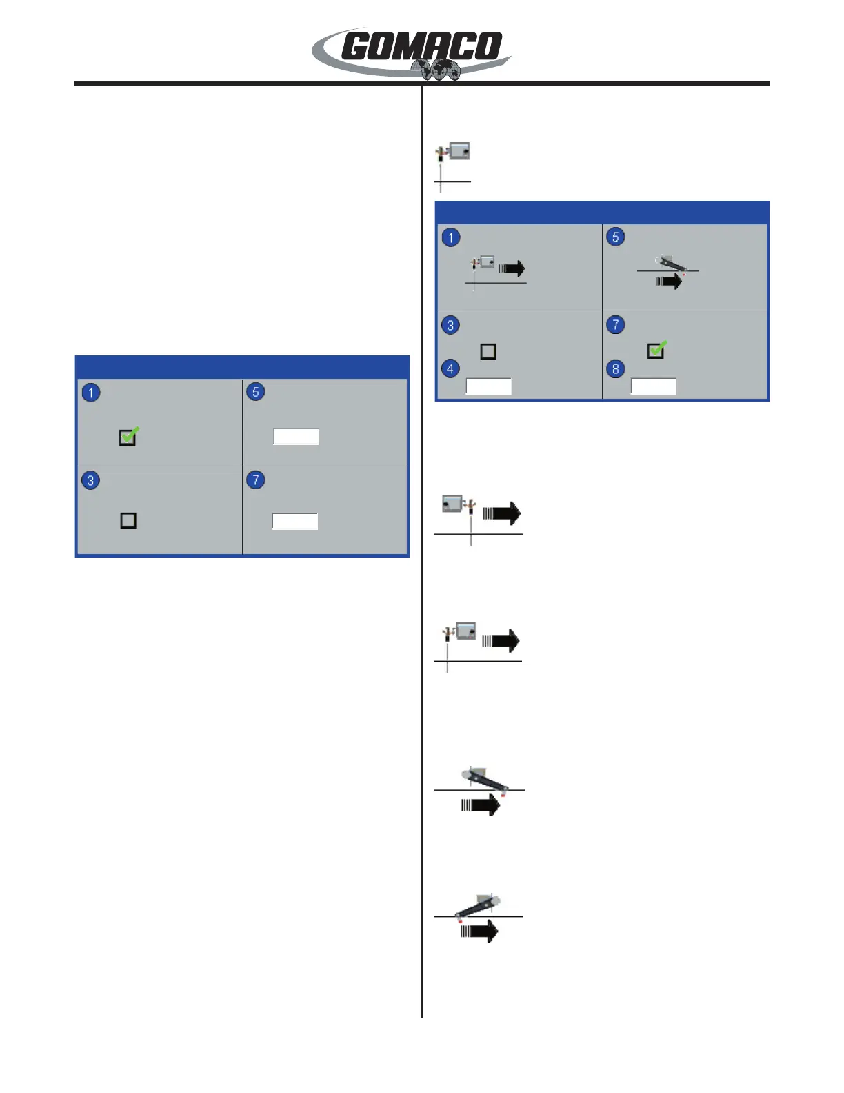
Used to set the steer and elevation sensors for push
or pull sensor wand orientation. Also used to turn the
bump lters on or off and adjusts the sensitivity level of
the bump lters.
220-0086a
Press the number 1 button to select the steering
sensors. In the push mode, the round sensor wand
will appear ahead of the sensor icon.
220-0087a
In the pull mode, the round sensor wand will appear
behind the sensor icon. Use the up (▲) or down (▼)
button to toggle between push or pull. Both steering
sensor wands must face the same direction.
220-0088a
Press the number 5 button to select the elevation
sensors. In the push mode, the round tube on the
sensor wand will appear ahead of the sensor icon.
220-0089a
In the pull mode, the round tube on the sensor wand
will appear behind the sensor icon. Use the up (▲) or
down (▼) button to toggle between push or pull. All
elevation sensor wands must face the same direction.
 Loading...