Commander III
2-28
Test menu:
Distance display
220-0068
103G+
Distance
Encoder 1 Encoder 2 Average
0 0 0
3318.40
ft
ft/min
0.0
Calibration
Factor
1.267 1.267
Pulses/ft
Pulses/m
1200
3937
103G+
Indicates the status of all distance related devices.
The top line of boxes indicate the encoder signals
during operation. A green box will indicate when the
encoder is turned “on” in the Setup Menu. The average
box indicates the numerical average if both encoders
are in operation.
Distance traveled is monitored in the left center box
and may be cleared to zero in the Setup Menus. The
right center box monitors the current travel speed of
the machine.
The calibration factor, pulses/foot or pulses/meter
values are set when the encoders are calibrated
during initial setup (see the Setup Menus for more
information.
Press the escape button (ESC) to return to the test
menu.
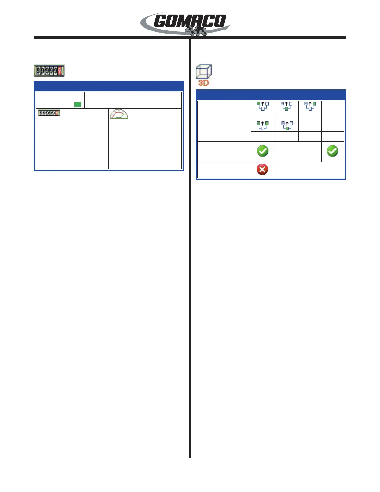
Test Menu:
3D display
220-0027
072G+
3D
0
0
0
0
0
Elevation
Steer
Communication Event
Station
Stop
072G+
Rx: 0 ms
Rx:
0 ms
0
Shows the elevation command and the steer
command data from the stringless control system.
The elevation and steer Rx data values indicate the
number of milliseconds (ms) since the last command
message was received from the 3D control system.
The values can be used to diagnose communication
problems with the 3D system.
The elevation and steer input signals will be at 465
when no correction is called for (center). The elevation
signals will vary ± 200 from 465. The steering signals
will vary ± 240 from 465. Without input signals from
the system all values will be 0.
The communication box indicates that positioning
data is being transmitted between the 3D controller
and the machine controller. A green check mark icon
will indicate that communication is active while a red
X icon will indicate that communication has been
interrupted.
The event box indicates that a momentary signal has
been sent to activate a device on the machine (e.g.
bar inserter). A green check mark icon will appear
when the event signal is momentarily activated while
a red X icon will indicate that the signal is currently
inactive.
The stop box indicates that a stop operation command
has been received from the 3D controller. A green
check mark will normally be indicated, while a red X
will appear when a stop command is received.
The Station value will be provided by Leica PaveSmart
software and corresponds to the location of jobsite
stations.
 Loading...