Commander III
2-26
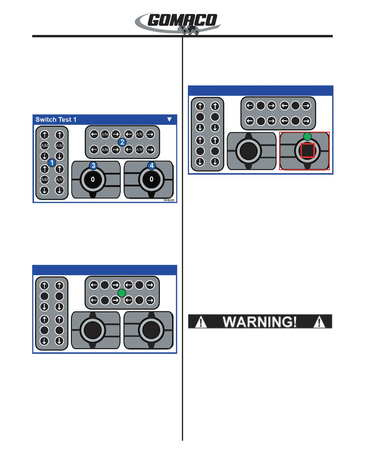
in the top right corner of each display. Switch Test 1
shows the status of switches for elevation, steering
and the multi-function switch and dial assemblies.
The switch icons will indicate green when the
corresponding switch is pressed. Rotating the steer
dial left from center should indicate a range from
0 to -100 and should indicate a range of 0 to 100
when turned right from center. The travel dial should
indicate a range from 0 to 100.
G+0226
The numbers assigned to each controller (in blue) will
only appear if a CAN communication failure occurs
in one of the devices shown above. If a CAN button
controller fails (timeout), the switch test screen can be
used to override the functions of the failed controller.
To activate the simulation mode, disconnect the failed
device.
g+0227
Switch Test 1
▼
G+0227
A/M
A/M
A/M
A/M
A/M A/M
A/MA/M
0
0
6
Depress and hold the number button that corresponds
to the number on the device icon (in this example, #2).
Continue to hold the number button until the number
icon changes to green (approximately 5 seconds) and
the number changes to the original number plus 4 (in
this example, #6) to activate the "Sim Mode". The
"Sim Mode" can be active for more than one control at
a time.
Note: The "Sim Mode" is used to temporarily
operate the machine until it can be repaired. For
example, if the failure occurs during pouring
operations, the "Sim Mode" can be used to pour
the remaining concrete.
g+0228
Switch Test 1
▼
G+0228
A/M
A/M
A/M
A/M
A/M A/M
A/MA/M
0
15
8
Once a "Sim Mode" is active, the critical fault can
be cleared and the machine operations can resume.
Buttons 6-8 are used to select which control is active.
Depress the number button that corresponds to the
number (in green) on the failed device. The defective
control icon will be surrounded in red. A red cursor
will surround one of the individual buttons on the
controller. Use the ◄ or ► arrow buttons to move the
cursor to the desired button. Depress the OK button
to activate the selected button. To move to a different
control, depress the number button (in green) that
corresponds to the control.
Note: The number button must be green to
operate the control from the test display. If the
number button is not green, depress the number
that corrresponds to the blue button for 5 seconds,
until the number button turns green.
w0380
If the "Sim Mode" is being used for the travel
buttons, keep the cursor over the travel variable
button, the N (neutral) button, or the run/standby
button so that pressing the OK button will stop
the machine immediately in case of emergency.
Pressing the Emergency Stop button on the
console will also stop the machine.
If the button selected is the travel variable encoder, or
the steering encoder, use the ▼ or ▲ arrow buttons to
adjust the encoder value. Depressing the OK button
will reset the value of the encoder back to 0.0. If
the "Sim Mode" is being used for the travel buttons,
always keep the cursor over the travel variable button,
the N (neutral) button, or the run/standby button so
 Loading...