Commander III
2-25
Test menu:
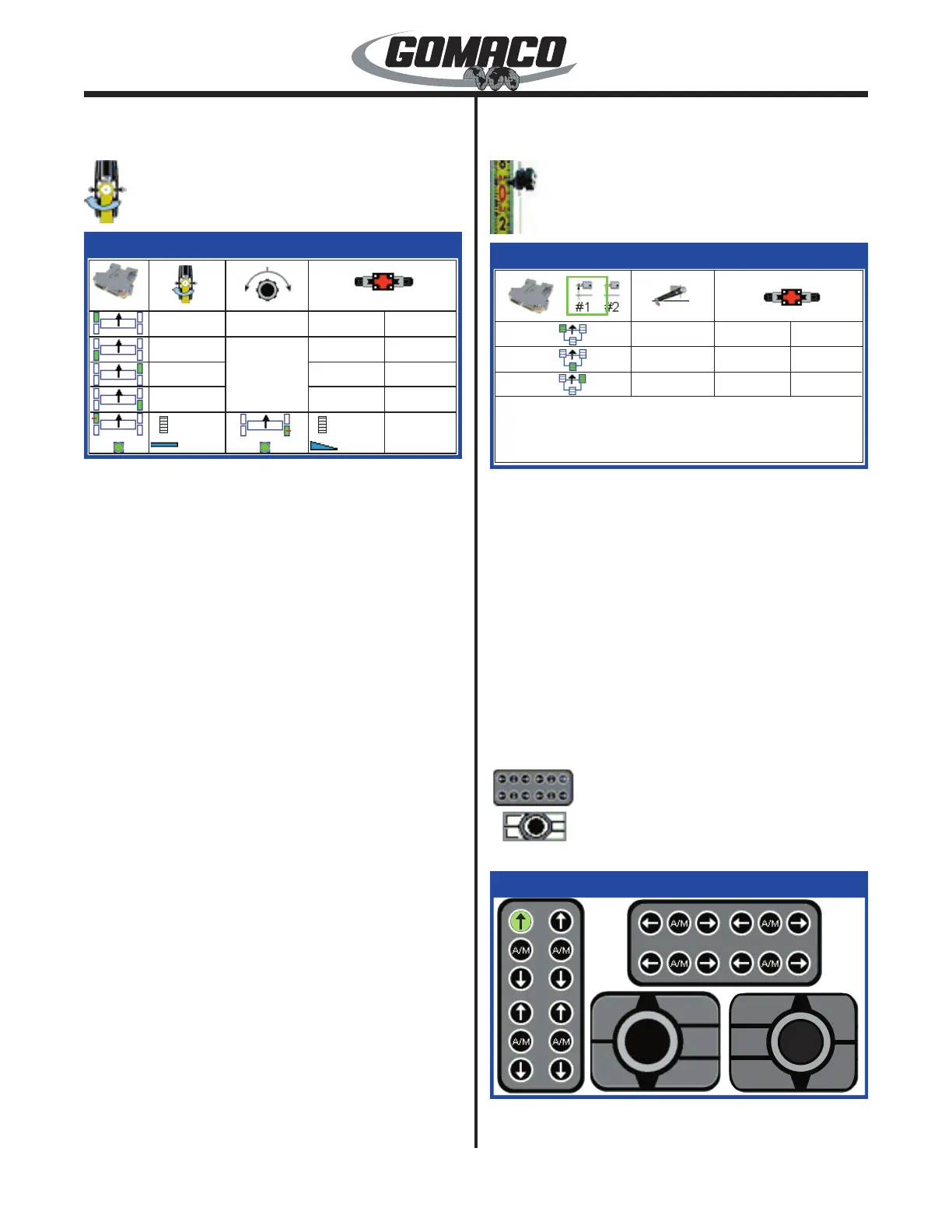
Steer power test display
070
171G+
Steer Power
0.00v0
0.00v
0.00v
0.00v
0.00v
0.00v
0.00v0.00v
2.48v
2.37v
2.48v
2.16v
0.00°
0.00°
0.00°
1.35°
171G+
2.46v 2.32v
Monitors output voltages for the steering system.
The left column indicates icons for each monitored
controller. The second column monitors smart cylinder
output (0.26 to 4.65 volts normally). The third column
monitors steer sensor output (1.2 to 3.8 volts normally)
or steer dial signal (0 to ±100). The right columns
monitor the (←) left or (→) right output voltages to the
steer valves (0.0 to 4.4 volts normally).
If the steer select switch is in one of the manual steer
positions, the manual steer dial icon will be at the top
of the third column, which shows the signal (0 to ±100)
from the manual steer dial potentiometer.
The bottom row will show heavy steer assist
parameters when 4-track machine type is selected.
The rst and third columns indicate left front and
right rear heavy steer assist slope sensor feedback
(indicated as a voltage that increases or decreases in
value). A green LED light indicates an active signal
communicated from the sensor. The second and
fourth columns compare track degree of rotation and
percentage of slope from the sensors on the legs.
Degree of rotation should vary from 0.00 up to ±10.00
degrees and slope should vary from 0.00 up to ±10.00
percent during normal operation.
Press the escape button (ESC) to return to the test
menu.
Test menu:
Elevation power test display
071
068G+
Elevation Power
1.05v0.00v
0.00v
0.03v
0.00v
0.00v
0.00v
0.00v
0.00v
068G+
Monitors output voltages for the elevation system.
The left column indicates icons for each monitored
controller. The second column monitors elevation
sensor output (1.2 to 3.8 volts normally). The right
columns monitor the (↑) or (↓) output voltages to the
elevation valves (0.0 to 4.4 volts normally). Press the
escape button (ESC) to return to the test menu.
Note: The digital slope sensor is connected to the
CAN communication network and will not output a
sensor voltage.
Test menu:
Switch test displays
073
040G+
One of three status displays that are accessed by
pressing the ▲ or ▼ navigation buttons as indicated
 Loading...