Commander III
2-24
161G+
Steer Thresholds
29
29
28
29
= +/-
200
-200
0 mV
161G+
Mode
A pop up screen will appear whenever the run/standby,
manual steer or travel switches are pressed. This
allows the operator to see currently active automatic,
fault, travel and steer modes when viewing displays
other than the Run Menu.
Main Menu
Test menu
065G+
Test Menu
001G+
5
4
321
6 7 8
Controller Power
065G+
The various test sub-menus allow a service
technician to monitor controller, steer, elevation and
travel voltages. The sub-menus also monitor input
and output status signals for the tracks, conveyor,
auger, trimmer and vibrators. Distance input/output,
3D signals and Engine parameters may also be
monitored. Shaded sub-menu icons are not available
or not activated for the machine model.
Press the navigation buttons to move the red selection
cursor to the desired sub-menu. The title of the
selected sub-menu will appear in the status bar at the
bottom of the screen. Press the OK button to enter a
sub-menu (or press a number button to bypass cursor
navigation and directly enter a sub-menu). Press the
escape button (ESC) to return to the main menu.
Three track icons and voltages are shown in most
of the following displays. Four track icons and
voltages will appear when four track conguration is
selected. Descriptions for all available assessories or
options may not appear in the displays shown below
(contact GOMACO for more information). Below is a
description of each of the test displays:
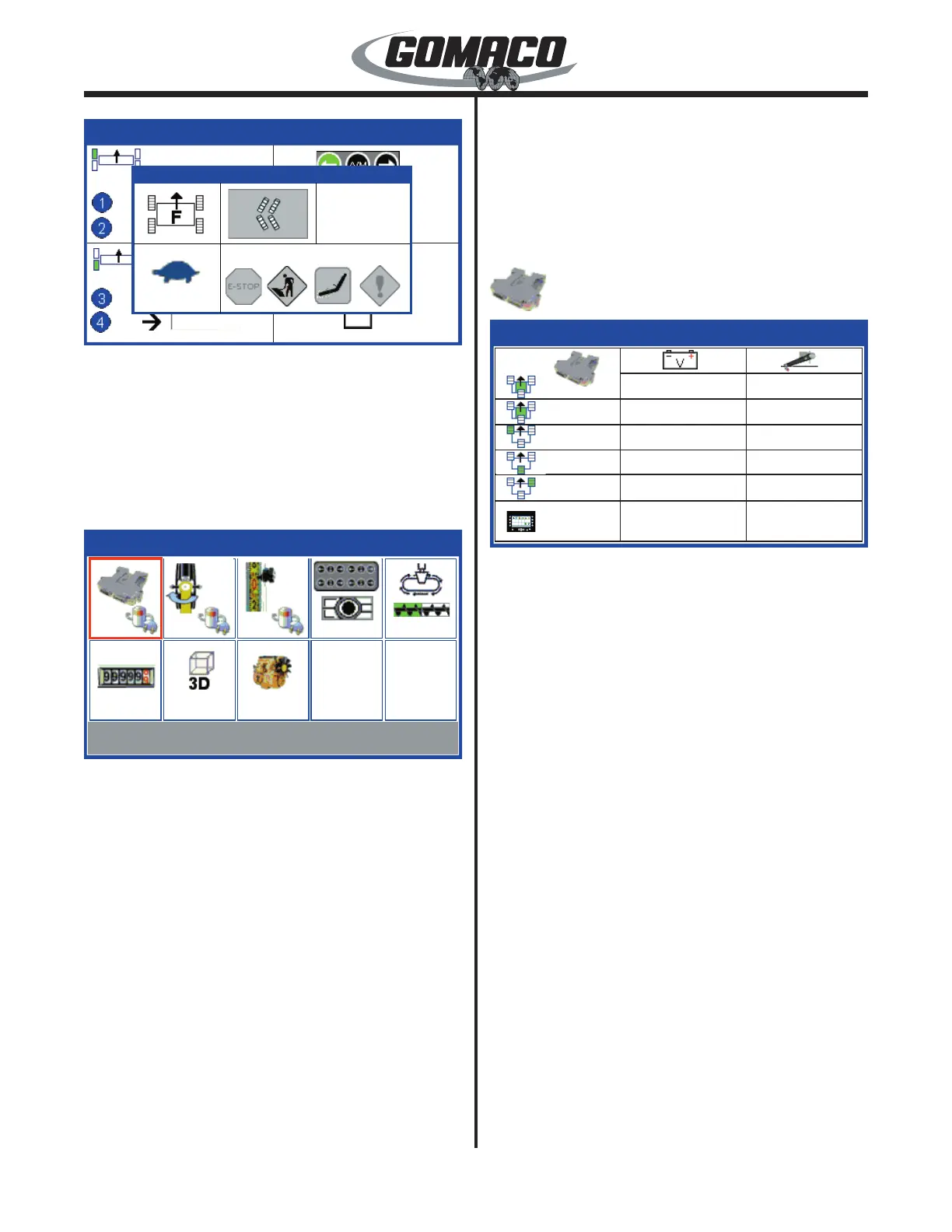
Test menu:
Controller power test display
072
066G+
Controller Power
11.97v
4.97v
4.98v
4.99v
4.97v
4.99v
11.83v
11.98v
11.73v
12.06v
11.67v
066G+
1
2
Controller power monitors power supply voltages. The
left column indicates machine icons for each controller
and the G+ display. Main controllers are identied
with green shading in the center of the icon followed
by a number. Controllers for elevation and steering
are identied with a green shaded track. The center
column shows the corresponding battery voltage
supplied to each controller (9.0 to 16.0 volts normally).
The right column shows the sensor power supply (4.75
to 5.25 volts normally) available from each controller to
the corresponding control dials or sensors. Press the
escape button (ESC) to return to the test menu.
 Loading...