Commander III
2-4
of cut, grade density and forward travel speed. Relief
pressure setting for the trimmer system is 2600 psi
(179 bar).
When the machine is equipped with the auxiliary
vibrator manifold, the trimmer hydraulic system is used
to operate the auxiliary vibrators. The trimmerhead
pressure gauge will monitor the normal operating
pressure range from 500 to 1500 psi (34 to 103.4 bar).
Relief pressure setting for the auxiliary vibrator system
is 1850 psi (127 bar).
Conveyor Pressure Gauge: Monitors the amount
of pressure required to operate the charging
conveyor. Amount of pressure required will depend
on the amount of concrete on the conveyor. Normal
operating pressure range is 500 to 2000 psi (34 to 138
bar). Relief pressure setting for the conveyor system
is 2400 psi (166 bar).
Note: When the machine is equipped with a
paving form, the conveyor pressure gauge is used
to monitor the pressure of the dual paving augers
in the slipform mold.
Auger Pressure Gauge: Monitors the amount of
pressure required to operate the auger. Normal
operating pressure range is 500 to 1800 psi (34 to 124
bar). Relief pressure setting for the auger system is
2350 psi (162 bar).
Note: When the machine is equipped with a
paving form, the auger pressure gauge is used
to monitor the pressure of the tamper bar in the
slipform mold.
Lift Pressure Gauge: Monitors the amount of
hydraulic pressure available for machine elevation and
steering control. Normal lift pressure is 2000 psi (138
bar).
Note: If the lift pressure drops below 1500 PSI
(103 bar), the machine control may become slow.
Track Pressure Gauge: Monitors the amount of
pressure required to operate the track drive system in
forward or reverse. Normal operating pressure range
is 500 to 1800 psi (48 to 124 bar). Relief pressure
setting for the tractive system is 2500 psi (173 bar).
Drawbar Pressure Gauge: Monitors the amount of
pressure applied to the hydraulic cylinder holding the
front of the slipform mold down in contact with the
concrete. The regulated pressure range is 0 to 800 psi
(0 to 55 bar).
Form Hold-down Pressure Gauge: Monitors the
amount of pressure applied to the hydraulic cylinder
holding the rear of the slipform mold down in contact
with the concrete. The regulated pressure range is 0
to 800 psi (0 to 55 bar).
Form Hold-Over Pressure Gauge (Option):
Monitors the amount of pressure applied to the
hydraulic cylinder holding the rear of the slipform mold
in contact with an existing concrete surface for scab on
placement. The regulated pressure range is 0 to 600
psi (0 to 41 bar).
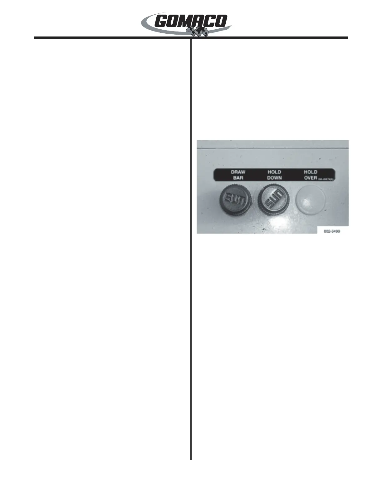
002-3499
Drawbar Hold Down Pressure Control Valve: Used
to adjust the amount of pressure holding the front of
the slipform mold down on the concrete. Pressure
adjusts from 30 to 800 psi (2.1 to 55 bar) by turning
the control dial clockwise to increase pressure and
counterclockwise to decrease pressure.
Hold Down Pressure Control Valve: Used to adjust
the amount of pressure holding the rear of the slipform
mold down on the concrete. Pressure adjusts from
30 to 800 psi (2.1 to 55 bar) by turning the control dial
clockwise to increase pressure and counterclockwise
to decrease pressure.
Holdover Pressure Control Valve (optional): Used
to adjust the amount of pressure holding the rear
of the slipform mold against the existing roadway.
Pressure adjusts from 30 to 600 psi (2.1 to 41.4
bar) by turning the control dial clockwise to increase
pressure and counterclockwise to decrease pressure.
 Loading...