30
Natural Gas Minimum: 4.5" w.c. Maximum: 10.0" w.c.
Propane Gas Minimum: 11.0" w.c. Maximum: 13.0" w.c.
INLET GAS SUPPLY PRESSURE
HIGH ALTITUDE DERATE
When this furnace is installed at high altitude, the appropriate
High Altitude orifice kit must be applied. This is required due to
the natural reduction in the density of both the gas fuel and com-
bustion air as altitude increases. The kit will provide the proper
design certified input rate within the specified altitude range.
High altitude kits are purchased according to the installation alti-
tude and usage of either natural or propane gas. Consult the
furnace Specification Sheet for appropriate kits.
Do not derate the furnace by adjusting the manifold pressure to
a lower pressure than specified on the furnace rating plate. The
combination of the lower air density and a lower manifold pres-
sure will prohibit the burner orifice from drawing the proper amount
of air into the burner. This may cause incomplete combustion,
flashback, and possible yellow tipping.
In some areas the gas supplier may artificially derate the gas in
an effort to compensate for the effects of altitude. If the gas is
artificially derated, the appropriate orifice size must be deter-
mined based upon the BTU/ft
3
content of the derated gas and
the altitude. Refer to the National Fuel Gas Code, NFPA 54/ANSI
Z223.1, and information provided by the gas supplier to deter-
mine the proper orifice size.
A different pressure switch may be required at high altitude re-
gardless of the BTU/ft
3
content of the fuel used. Consult the
furnace Specification Sheet for pressure switch.
PROPANE GAS CONVERSION
WARNING
P
OSSIBLE
PROPERTY
DAMAGE
,
PERSONAL
INJU R Y
OR
DEATH
MAY
OCCUR
IF
THE
CORREC T
CONVERSIO N
KITS
ARE
NOT
INSTALLED
.T
HE
APPROPRIATE
KITS
MUST
BE
APPLIED
TO
ENS U RE
SAFE
AND
PROPER
FURNAC E
OPERATION
.A
LL
CONVERSIO NS
MUST
BE
PERFORMED
BY
A
QU A LIFIED
INSTALLER
OR
SERVICE
AGENCY
.
This unit is configured for natural gas. The appropriate
manufacturer’s propane gas conversion kit, must be applied for
propane gas installations. Refer to the Propane Gas and/or High
Altitude Installations for details.
Consult the furnace Specification Sheet for a listing of appro-
priate kits. The indicated kits must be used to insure safe and
proper furnace operation. All conversions must be performed by
a qualified installer, or service agency.
GAS VALVE
This unit is equipped with a 24 volt gas valve controlled during
furnace operation by the integrated control module. As shipped,
the valve is configured for natural gas. The valve is field convert-
ible for use with propane gas by replacing the regulator spring
with a propane gas spring from an appropriate manufacturer’s
propane gas conversion kit. Taps for measuring the gas supply
pressure and manifold pressure are provided on the valve.
The gas valve has a manual ON/OFF control located on the valve
itself. This control may be set only to the “ON” or “OFF” position.
Refer to the lighting instructions label or Startup Procedure &
Adjustment for use of this control during start up and shut down
periods.
GAS PIPING CONNECTIONS
T
O
AVOID
POSSIBLE
UNSATISFACTORY
OPERATION
OF
EQU IP MENT
DAMAGE
DUE
TO
UN D ER FIR IN G
OR
EQUI P M EN T
,
USE
THE
PROPER
SIZE
OF
NATURAL
/
PROPA NE
GAS
PIPING
NEEDED
WHEN
RUNNING
PIPE
FROM
THE
METER
/
TAN K
TO
THE
FURNAC E
.
WARNING
When sizing a trunk line, be sure to include all appliances which
will operate simultaneously when sizing a trunk line.
The gas piping supplying the furnace must be properly sized
based on the gas flow required, specific gravity of the gas, and
length of the run. The gas line installation must comply with local
codes, or in their absence, with the latest edition of the National
Fuel Gas Code, NFPA 54/ANSI Z223.1.
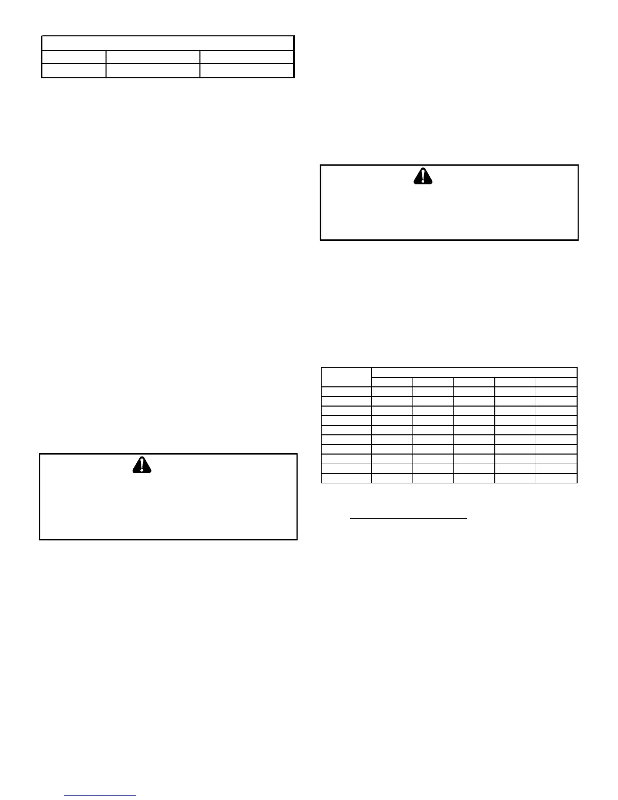
Natural Gas Capacity of Pipe
In Cubic Feet of Gas Per Hour (CFH)
Length of Nominal Black Pipe Size
Pipe in Feet 1/2" 3/4" 1" 1 1/4" 1 1/2"
10 132 278 520 1050 1600
20 92 190 350 730 1100
30 73 152 285 590 980
40 63 130 245 500 760
50 56 115 215 440 670
60 50 105 195 400 610
70 46 96 180 370 560
80 43 90 170 350 530
90 40 84 160 320 490
100 38 79 150 305 460
(Pressure 0.5 psig or less and pressure drop of 0.3" W.C.; Based on
0.60 Specific Gravity Gas)
CFH =
BTUH Furnace Input
Heating Value of Gas (BTU/Cubic Foot)
To connect the furnace to the building’s gas piping, the installer
must supply a ground joint union, drip leg, manual shutoff valve,
and line and fittings to connect to gas valve. In some cases, the
installer may also need to supply a transition piece from 1/2" pipe
to a larger pipe size.
The following stipulations apply when connecting gas piping. Re-
fer to Gas Piping Connections figure for typical gas line connec-
tions to the furnace.
• Gas piping must be supported external to the furnace
cabinet so that the weight of the gas line does not
distort the burner rack, manifold or gas valve.
• Use black iron or steel pipe and fittings for building piping.
Where possible, use new pipe that is properly chamfered,
reamed, and free of burrs and chips. If old pipe is used,
be sure it is clean and free of rust, scale, burrs, chips, and
old pipe joint compound.