EasyManua.ls Logo

Goodman *CVC96 - User Manual

Goodman *CVC96
60 pages
Print Icon
To Next Page IconTo Next Page
Loading...
IOG-2008A
12/14
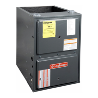
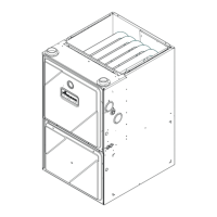
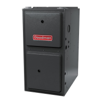
(Type FSP CATEGORY IV Direct
or Non Direct Vent Air Furnace)
Installer:
Affix all manuals
adjacent to the unit.
A
s a professional installer you have an obligation to know
the product better than the customer. This includes all safety
precautions and related items.
Prior to actual installation, thoroughly familiarize yourself
with this Instruction Manual. Pay special attention to all
safety warnings. Often during installation or repair it is
possible to place yourself in a position which is more
hazardous than when the unit is in operation.
Remember, it is your responsibility to install the product
safely and to know it well enough to be able to instruct a
customer in its safe use.
Safety is a matter of common sense...a matter of thinking
before acting. Most dealers have a list of specific good
safety practices...follow them.
The precautions listed in this Installation Manual are intended
as supplemental to existing practices. However, if there is
a direct conflict between existing practices and the content
of this manual, the precautions listed here take precedence.
RECOGNIZE THIS SYMBOL
AS A SAFETY PRECAUTION.
*NOTE: Please contact your distributor or our website for
the applicable Specification Sheet referred to in this manual.
TABLE OF CONTENTS
SAFETY CONSIDERATIONS.................................... 3
SHIPPING INSPECTION ......................................... 4
ELECTROSTATIC DISCHARGE (ESD) PRECAUTIONS ................. 4
TO THE INSTALLER........................................... 4
PRODUCT DESCRIPTION ....................................... 4
FEATURES ................................................... 4
PRODUCT APPLICATION ....................................... 5
LOCATION REQUIREMENTS & CONSIDERATIONS ........... 6
CLEARANCES AND A CCESSIBILITY ................................ 7
EXISTING FURNACE REMOVAL .................................. 7
THERMOSTAT LOCATION ....................................... 9
COMBUSTION & VENTILATION AIR REQUIREMENTS ................ 9
INSTALLATION POSITIONS .................................... 9
HORIZONTAL APPLICATIONS & CONSIDERATIONS ........10
FURNACE SUSPENSION........................................10
FRONT COVER PRESSURE SWITCH TUBE LOCATION ..............10
DRAIN TRAP AND LINES ......................................10
LEVELING ..................................................10
ALTERNATE VENT/FLUE AND COMBUSTION AIR CONNECTIONS ....10
ALTERNATE ELECTRICAL AND GAS LINE CONNECTIONS ............11
DRAIN PAN .................................................11
FREEZE PROTECTION .........................................11
PROPANE GAS/HIGH ALTITUDE INSTALLATIONS ..........11
VENT/FLUE PIPE & COMBUSTION AIR PIPE ................12
DUAL CERTIFICATION: NON-DIRECT/DIRECT VENT ..............12
MATERIALS AND JOINING METHODS ............................12
PROPER VENT/FLUE AND COMBUSTION AIR PIPING PRACTICES ....13
TERMINATION LOCATIONS .....................................13
CANADIAN VENTING REQUIREMENTS............................14
STANDARD FURNACE CONNECTIONS ............................14
VENT/FLUE PIPE ...........................................14
COMBUSTION AIR PIPE DIRECT VENT INSTALLATION...............14
NON-DIRECT VENT (SINGLE PIPE) PIPING .....................16
VENT/INTAKE TERMINATIONS FOR INSTALLATION
OF
MULTIPLE DIRECT VENT FURNACES ....................19
CONCENTRIC VENT TERMINATION ..............................19
SIDE WALL VENT KIT .......................................19
CONDENSATE DRAIN LINES & DRAIN TRAP ................19
GENERAL DRAIN INFORMATION ................................19
FIELD SUPPLIED DRAIN ......................................20
UPFLOW MODEL INSTALLED VERTICALLY .......................20
DRAIN EXITING RIGHT SIDE ...................................20
DRAIN EXITING LEFT SIDE ....................................20
UPFLOW MODEL INSTALLED HORIZONTALLY
WITH
RIGHT SIDE DOWN ...............................21
UPFLOW MODEL INSTALLED HORIZONTALLY WITH LEFT SIDE DOWN .21
COUNTERFLOW MODEL INSTALLED VERTICALLY..................22
I
NSTALLATION
I
NSTRUCTIONS
FOR
*CVC96 & *MVC96
T
WO
-S
TAGE
G
AS
F
URNACE
These furnaces comply with requirements em-
bodied in the American National Standard / Na-
tional Standard of Canada ANSI Z21.47·CSA-2.3
Gas Fired Central Furnaces.
5151 San Felipe Suite 500
Houston, TX 77056
www.goodmanmfg.com • www.amana-hac.com
© 2014 Goodman Manufacturing Company, L.P.
is a registered trademark of Maytag Corporation or its related companies and is used under license. All rights reserved.

Table of Contents

Questions and Answers

Summary

Safety Considerations

Caution: Frozen and Burst Water Pipe Hazard

Warnings regarding frozen pipes and potential water damage.

Warning: Electrical Shock and Property Damage

Warnings about electrical shock and property damage.

Electrostatic Discharge (ESD) Precautions

Location Requirements & Considerations

Warning: Installation Precautions

Critical warnings about equipment damage, property damage, and injury.

Clearances and Accessibility

Combustion & Ventilation Air Requirements

Propane Gas;High Altitude Installations

Vent;Flue Pipe & Combustion Air Pipe

Proper Vent;Flue and Combustion Air Piping Practices

Termination Locations

Non-Direct Vent Installations

Non-Direct Vent (Single Pipe) Piping

Direct Vent (Dual Pipe) Piping

Condensate Drain Lines & Drain Trap

Electrical Connections

115 Volt Line Connections

Proper procedures for high voltage connections.

24 Volt Thermostat Wiring

Fossil Fuel Applications

Gas Supply and Piping

High Altitude Derate

How altitude affects furnace operation and required adjustments.

Propane Gas Conversion

Steps for converting the furnace to propane.

Gas Piping Connections

Propane Gas Tanks and Piping

Gas Piping Checks

Circulating Air & Filters

Filters - Read This Section Before Installing the Return Air Duct Work

Startup Procedure & Adjustment

Drain Trap Priming

Crucial step to ensure proper drainage and operation.

Furnace Startup

Gas Supply Pressure Measurement

Gas Pressure Test

Specific test mode for checking gas pressure.

Gas Manifold Pressure Measurement and Adjustment

Gas Input Rate Measurement (Natural Gas Only)

Temperature Rise

Circulator Blower Speeds

ComfortNetTM System

CTKO* Wiring

ComfortNetTM Compatible Furnace with Non-ComfortNet Compatible Single-Stage Air Conditioner

ComfortNet System Advanced Features

Furnace Advanced Features Menus

Diagnostics

Accessing and interpreting fault codes.

Set-Up

Non-Comm Single Stage Air Conditioner Settings

Settings for non-communicating AC units.

Diagnostics

Network Troubleshooting

System Troubleshooting

Normal Sequence of Operation

Heating Mode

Operational steps during heating.

Cooling Mode

Operational steps during cooling.

Operational Checks

Safety Circuit Description

Integrated Control Module

Function and role of the main control module.

Troubleshooting

Diagnostic Chart

Reference for interpreting error codes.

Resetting From Lockout

Procedures for clearing furnace lockout conditions.

Maintenance

Annual Inspection

Recommended annual service checklist.

Before Leaving an Installation

Repair and Replacement Parts

Dip Switches

Status Codes

Troubleshooting Chart

Wiring Diagram

Special Instructions for Products Installed in the State of Massachusetts

Goodman *CVC96 Specifications

General IconGeneral
ModelCVC96
TypeGas Furnace
Efficiency RatingUp to 96% AFUE
Heating Capacity40, 000-120, 000 BTU/h
StagesTwo-stage
Blower MotorECM
Motor TypeECM
Blower TypeMulti-speed
Fuel TypeNatural Gas
Heat ExchangerStainless Steel
Warranty10-Year Parts Limited Warranty

Related product manuals