20
FIELD SUPPLIED DRAIN
Drain the furnace and air conditioning coil if applicable, in com-
pliance with code requirements. In horizontal or counterflow in-
stallations, a field installed rubber coupling will allow the drain
trap to be removed for cleaning. The drain trap must be primed
before initial furnace start up. When an air conditioning coil
drain is connected to the field supplied furnace drain, it must be
vented, with an open tee installed at a height no higher than the
bottom of the furnace collector box to prevent air conditioning
condensate from backing up into the furnace if the common drain
was blocked.
UPFLOW MODEL INSTALLED VERTICALLY
The trap and factory installed hoses remain as shipped. The fur-
nace drain may exit either the right or left side of the furnace
cabinet.
DRAIN EXITING RIGHT SIDE
1. Locate and Install the 45º pipe / hose drain coupling from
the outside of the cabinet (barbed end goes in the cabinet)
through hole in the right side of the cabinet and secure with
two field supplied #8 self-tapping screws (see Figure 22).
2. Locate the long drain hose #3 and cut at line “A” .
3. Install large end of hose #3 to trap outlet and secure with
1.25" clamp.
4. Install smaller end of hose #3 on 45º elbow and secure with
1" clamp.
5. Refer to Field Supplied Drain section for instructions on field
supplied / installed drain on outlet of furnace trap.
DRAIN EXITING LEFT SIDE
1. Install the 45 degree pipe / hose drain coupling
from the outside of the cabinet (barbed end goes
in the cabinet) through the hole in the left side of
the cabinet and secure with two field supplied #8
self-tapping screws (see Figure 22).
2. Locate the long drain hose #3 and cut at “B” line
for a 17.5" cabinet; cut at line “C” for a 21" cabinet;
do not cut for a “D” width cabinet.
3. Install large end of hose #3 to trap outlet and secure
with 1.25" clamp.
4. Install smaller end of hose #3 on 45º elbow and
secure with 1" clamp.
5. Refer to Field Supplied Drain section for instructions
on field supplied / installed drain on outlet of
furnace trap.
UPFLOW MODEL INSTALLED HORIZONTALLY WITH
RIGHT SIDE DOWN
Minimum 5 ½" clearance is required for the drain trap
beneath the furnace.
1. Remove the clamps from both ends of the drain
hoses.
2. Remove the two screws holding the drain trap to
the blower deck.
3. Remove the trap and two hoses from the blower deck
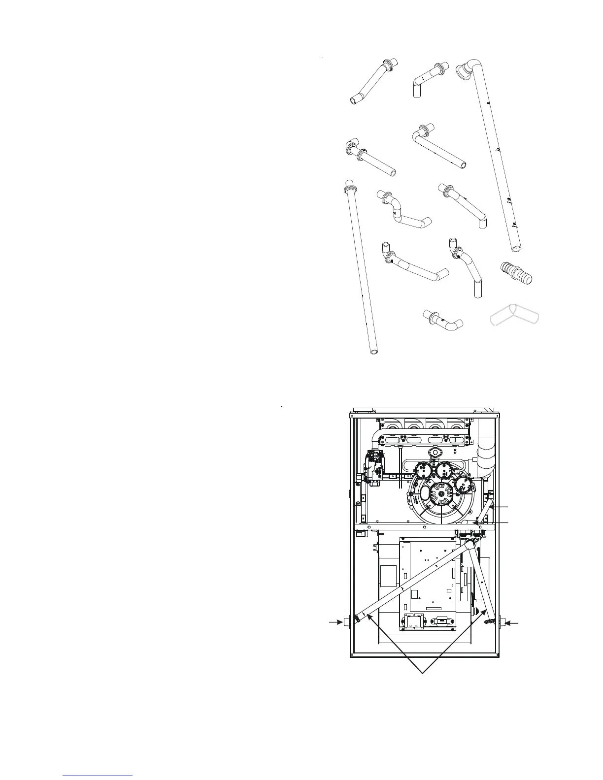
#
3
#1
#2
#4
#5
#
6
#7
#8
#9
#10
#11
100 Degree
Elbow
Coupling
Figure 21
NOTE:
and not all hoses will be shipped with all models.
Hoses are model specific
Installer selects right or left side drain
and installs this hose accordingly.
Hose #1
Hose #2
45 degree
barb-pipe
adapter
45 degree
barb-pipe
adapter
Figure 22