13
All 90° elbows must be medium radius (1/4 bend DWV) or long radius (Long sweep 1/4 bend DWV) types conforming to ASTM D3311.
A medium radius (1/4 bend DWV) elbow measures 3 1/16” minimum from the plane of one opening to the center line of the other
opening for 2” diameter pipe, and 4 9/16” minimum for 3” pipe.
PROPER VENT/FLUE AND COMBUSTION AIR PIPING PRACTICES
Adhere to these instructions to ensure safe and proper furnace
performance. The length, diameter, and number of elbows of the
vent/flue pipe and combustion air pipe (when applicable) affects
the performance of the furnace and must be carefully sized. All
piping must be installed in accordance with local codes and these
instructions.
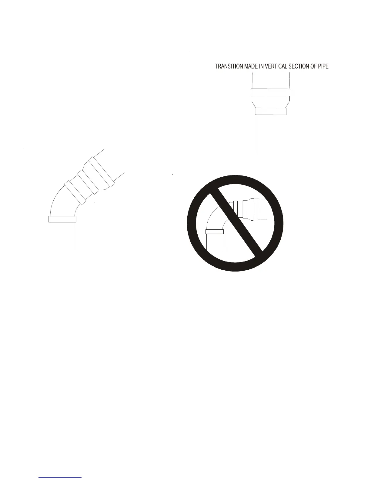
Some models require the use of 3” pipe. Do not transition
from a 2” to 3” pipe in a horizontal section of pipe as this
may create a water trap.
Piping must be adequately secured and supported to pro-
hibit sagging, joint separation, and/or detachment from
the furnace. Horizontal runs of vent/flue piping must be
supported every three to five feet and must maintain a 1/4 inch per foot downward slope, back towards the furnace, to properly
return condensate to the furnace’s drain system. Allowances should be made for minor expansion and contraction due to temperature
variations. For this reason, particular care must be taken to secure piping when a long run is followed by a short offset of less than
40 inches.
Precautions should be taken to prevent condensate from freezing inside the vent/flue pipe and/or at the vent/flue pipe termination.
All vent/flue piping exposed to freezing temperatures below 35°F for extended periods of time must be insulated with 1/2” thick
closed cell foam. Also all vent/flue piping exposed outdoors in excess of the terminations shown in this manual (or in unheated areas)
must be insulated with 1/2” thick closed cell foam. Inspect piping for leaks prior to installing insulation.
TERMINATION LOCATIONS
NOTE: Refer to Location Requirements and Considerations for combustion air contaminant restrictions.
The following bullets and diagram describe the restrictions concerning the appropriate location of vent/flue pipe and combustion air
intake pipe (when applicable) terminations. Refer to Non-Direct Vent (Single Pipe) Piping and Direct Vent (Dual Pipe) Piping located
in this section for specific details on termination construction.
• All terminations (flue and/or intake) must be located at least 12 inches above ground level or the anticipated snow level.
• Vent terminations (non-direct and direct vent) must terminate at least 3 feet above any forced air inlet located within 10
feet.
NOTE: This provision does not apply to the combustion air intake termination of a direct vent application.
• The vent termination of a non-direct vent application must terminate at least 4 feet below, 4 feet horizontally from, or 1 foot
above any door, window, or gravity air inlet into any building.
PREFERRED
Figure 4
TRANSITION NO LESS
THAN 45 DEGREES TO
HORIZONTAL PLANE TO
AVOID CREATING A WATER
TRAP IN VENT PIPING.
ACCEPTABLE
Figure 5
NO TRANSITION ON
HORIZONTAL PLANE,
THIS CREATES A
WATER TRAP AND
RESTRICTS FLUE
GASES
Figure 6