34
UPRIGHT INSTALLATIONS
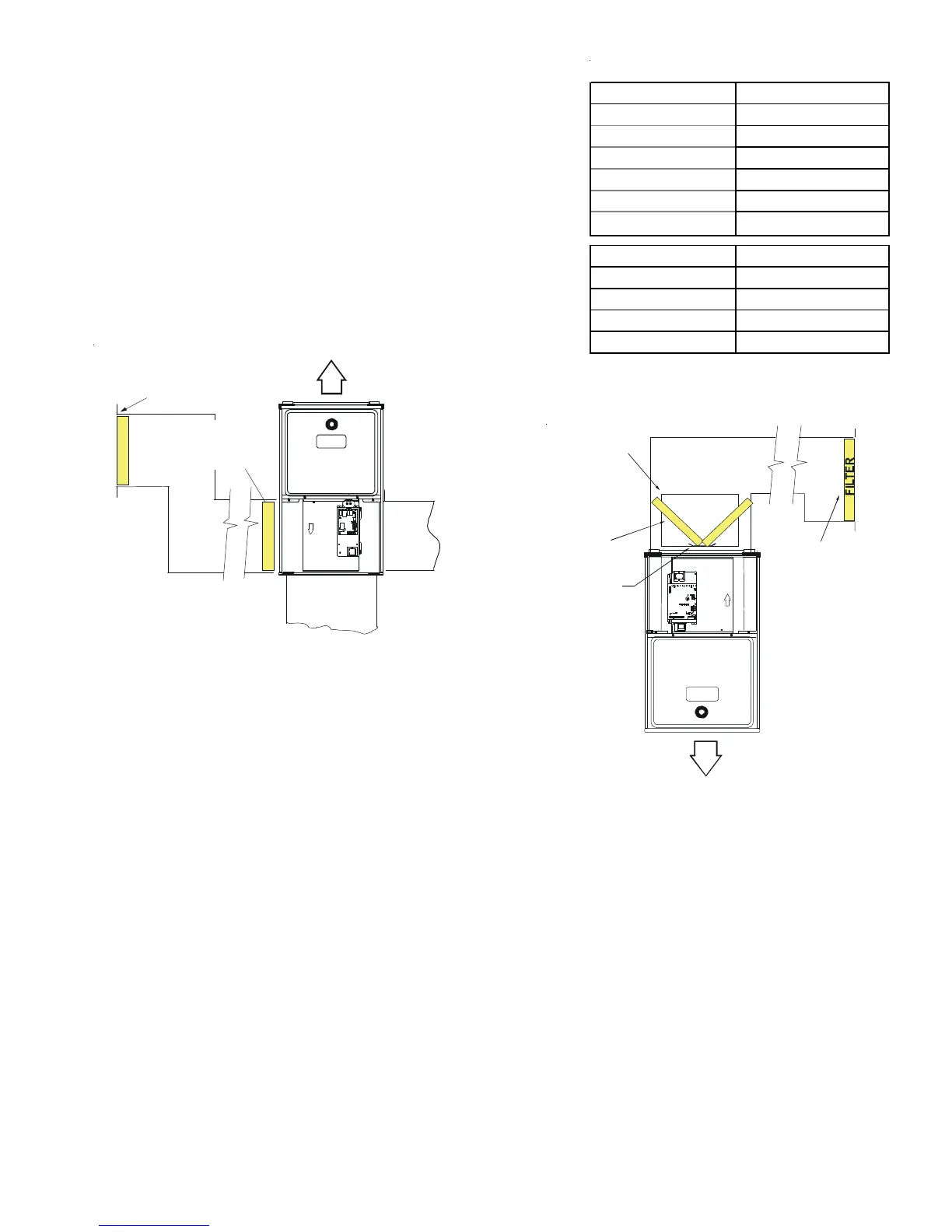
Depending on the installation and/or customer preference, differing filter ar-
rangements can be applied. Filters can be installed in the central return register
or a side panel external filter rack kit (upflows). As an alternative a media air
filter or electronic air cleaner can be used as the requested filter.
The following figure shows possible filter locations.
HORIZONTAL INSTALLATIONS
Filters must be installed in either the central return register or in the return
air duct work.
S
TARTUP
P
ROCEDURE
& A
DJUSTMENT
Furnace must have a 115 VAC power supply properly connected and grounded. Proper polarity must be maintained for correct
operation. In addition to the following start-up and adjustment items, refer to further information in Operational Checks section.
DRAIN TRAP PRIMING
The drain trap MUST be primed prior to furnace startup. To prime, fill both sides of the drain trap with water. This ensures proper
furnace drainage upon startup and prohibits the possibility of flue gases escaping through the drain system.
FURNACE OPERATION
Purge gas lines of air prior to startup. Be sure not purge lines into an enclosed burner compartment.
Check for leaks using an approved chloride-free soap and water solution, an electronic combustible gas detector, or other approved
method. Verify that all required kits (propane gas, high altitude, etc.) have been appropriately installed.
Model Minimum Filter Size
*M96VC0403BN**
20 X 24
*M96VC0603BN**
20 X 25
*M96VC0803BN**
18 X 36
*M96VC0804CN**
24 x 30
*M96VC1005CN**
24 X 36
*M96VC1205DN**
2 (20 X 25)
*C96VC0403BN**
20 X 24
*C96VC0603BN**
20 X 25
*C96VC0804CN**
18 X 36
*C96VC1005CN**
24 x 30
*C96VC1205DN**
2 (20 X 25)
[Based on 300 ft/min filter face velocity]
Change filters before occupants take ownership
Filter Sizing Chart
FILTER
AIR FLOW
CENTRAL
RETURN
GRILLE
FILTER
SIDE RETURN
EXTERNAL FILTER
RACK KIT
(EITHER SIDE)
Possible Upright Upflow
Figure 43
F
I
L
T
ER
AIR FLOW
CENTRAL
RETURN
GRILLE
RETURN
DUCT
FI
LT
ER
FILTER
SUPPORT
BRACKET
(Field Supplied)
FILTER
ACCESS
DOOR
Possible Upright Counterflow
Filter Locations
Figure 44