23
COUNTERFLOW MODEL INSTALLED HORIZONTALLY WITH LEFT SIDE DOWN
Minimum 5 ½" clearance is required for the drain trap beneath the furnace.
1. Remove hose clamps and hoses from trap.
2. Remove trap.
3. Remove plugs from left side of cabinet and
install in blower deck.
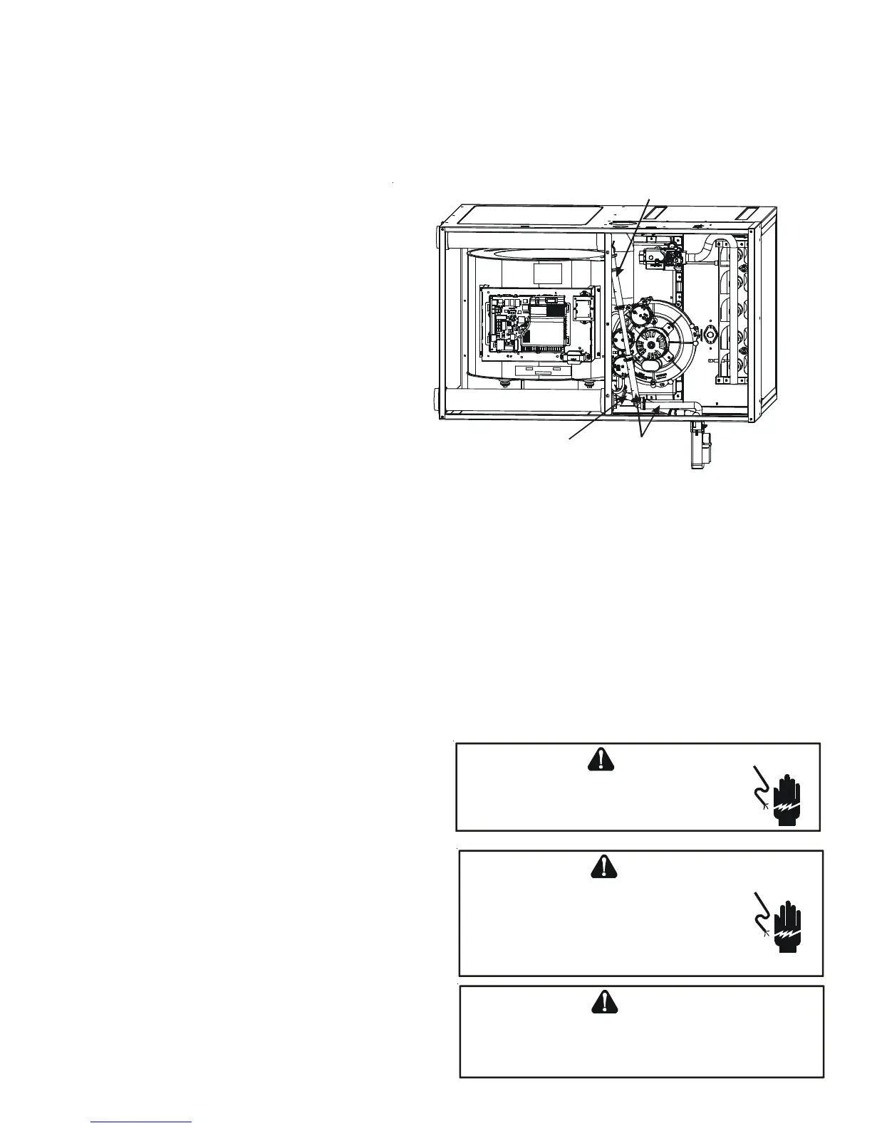
4. (Draining the Collector Box) Locate hose #4 and
place the radius end on the collector box drain
port, secure with a silver clamp.
5. Locate hose #2, insert from outside the cabinet
in the drain hole closest to the front of the
cabinet, insert a coupling and secure with a red
clamp.
6. Mate coupling to hose #4 and secure with a red
clamp.
7. (Draining the Vent Elbow) Remove plug from vent
– drain elbow side port.
8. Locate hose #4 and place radius end on the side
port of vent – drain elbow and secure with a red
clamp.
9. Install cap on vent drain elbow barb fitting
and secure with red clamp.
10.Insert PVC pipe into hose #4 and secure with a
red clamp.
11.Locate hose #5, insert it from outside the
cabinet in the drain hole farthest from the front of the cabinet.
12.Insert 100º elbow in hose #5 and secure with a red clamp.
13.Locate another hose #5 cut a 5.25" straight section and discard the radius end.
14.Connect the 5.25’ straight section to the 100º elbow and the PVC pipe and secure with red clamps.
15.Mate trap inlets and hoses and secure with silver clamps, drain trap outlet must point to the original bottom of the
furnace.
16.Secure trap to furnace using two screws removed in step 2.
17.Refer to Field Supplied Drain section for instructions on field supplied / installed drain on outlet of furnace trap.
E
LECTRICAL
C
ONNECTIONS
WIRING HARNESS
The wiring harness is an integral part of this furnace. Wires are
color coded for identification purposes. Refer to the wiring dia-
gram for wire routings. If any of the original wire as supplied
with the furnace must be replaced, it must be replaced with wir-
ing material having a temperature rating of at least 105° C. Any
replacement wiring must be a copper conductor.
115 VOLT LINE CONNECTIONS
Before proceeding with electrical connections, ensure that the
supply voltage, frequency, and phase correspond to that specified
on the unit rating plate. Power supply to the furnace must be NEC
Class 1, and must comply with all applicable codes. The furnace
must be electrically grounded in accordance with local codes or, in
their absence, with the latest edition of The National Electric
Code, ANSI NFPA 70 and/or The Canadian Electric Code CSA C22.1.
Use a separate fused branch electrical circuit containing properly
sized wire, and fuse or circuit breaker. The fuse or circuit breaker
Hose #4
Hose #5 x2
Hose #4
Figure 28
HIGH VOLTAGE !
T
O
AVOID
THE
RISK
OF
ELECTRICAL
SHOCK
,
WIRING
TO
THE
UNIT
MUST
BE
POLARIZED
AND
GROUNDED
.
WARNING
HIGH VOLTAGE !
T
O
AVOID
PERSONAL
INJURY
OR
DEATH
DUE
TO
ELECTRICAL
SHOCK
,
DISCONNECT
ELECTRICAL
POWER
BEFORE
SERVICING
OR
CHANGING
ANY
ELECTRICAL
WIRING
.
WARNING
L
ABEL
ALL
WIRES
PRIOR
TO
DISCONNECTION
WHEN
SERVICING
CONTROLS
. W
IRING
ERRORS
CAN
CAUSE
IMPROPER
AND
DANGEROUS
OPERATION
. V
ERIFY
PROPER
OPERATION
AFTER
SERVICING
.
CAUTION