10
I
NSTALLATION
P
OSITIONS
This furnace may be installed in an upright position or horizontal on either the left or right side panel. Do not install this furnace
on its back. For upright upflow furnaces, return air ductwork may be attached to the side panel(s) and/or basepan. For horizontal
upflow furnaces, return air ductwork must be attached to the basepan. For both upright or horizontal counterflow furnaces, return
ductwork must be attached to the basepan (top end of the blower compartment). NOTE: Ductwork must never be attached to the
back of the furnace. Contact your distributor for proper airflow requirements and number of required ductwork connections. Refer
to “Recommended Installation Positions” figure for appropriate installation positions, ductwork connections, and resulting airflow
arrangements.
H
ORIZONTAL
A
PPLICATIONS
& C
ONSIDERATIONS
When installing a furnace horizontally, additional con-
sideration must be given to the following:
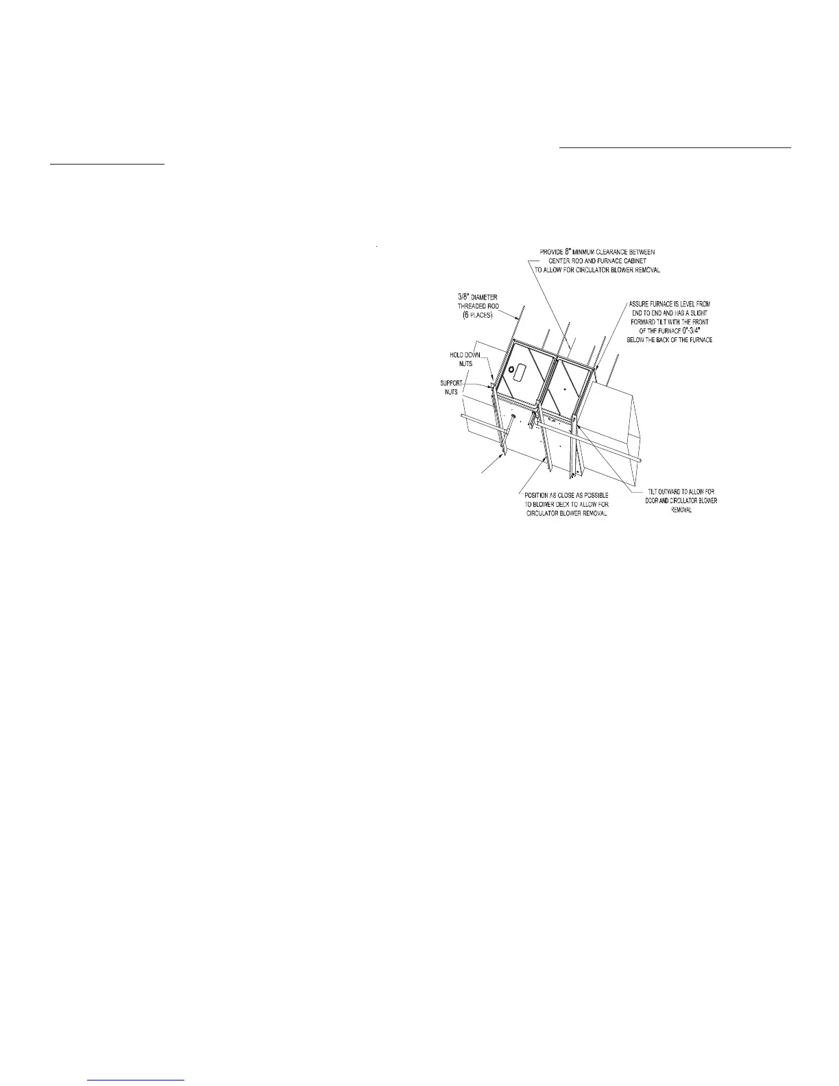
FURNACE S USPENSION
If suspending the furnace from rafters or joists, use 3/
8" threaded rod and 2”x2”x1/8” angle iron as shown in
the following diagram. The length of rod will depend on
the application and the clearances necessary.
If the furnace is installed in a crawl space it must be
suspended from the floor joist or supported by a con-
crete pad. Never install the furnace on the ground or
allow it to be exposed to water.
FRONT COVER PRESSURE SWITCH TUBE LOCATION
When an upflow model is installed horizontally with
left side down or a counterflow model is installed
horizontally with right side down, the front cover
pressure switch tube must be re-located to the lower port of the collector box cover.
1. Remove tube from front cover pressure switch and collector box cover.
2. Remove rubber plug from bottom collector box port and install on top collector box port.
3. Locate 24” x 1/4” tube in parts bag.
4. Install one end on front cover pressure switch.
5. Route tube to lower port on collector box cover and cut off excess tubing.
DRAIN TRAP AND LINES
In horizontal applications the condensate drain trap is secured to the furnace side panel, suspending it below the furnace. A minimum
clearance of 5 ½” below the furnace must be provided for the drain trap. Additionally, the appropriate downward piping slope must
be maintained from the drain trap to the drain location. Refer to Condensate Drain Trap and Lines for further details. If the drain trap
and drain line will be exposed to temperatures near or below freezing, adequate measures must be taken to prevent condensate from
freezing.
LEVELING
Leveling ensures proper condensate drainage from the heat exchanger and induced draft blower. For proper flue pipe drainage, the
furnace must be level lengthwise from end to end. The furnace should have a slight tilt from back to front with the access doors
downhill from the back panel approximately 1/2 to 3/4 inches. The slight tilt allows the heat exchanger condensate, generated in
the recuperator coil, to flow forward to the recuperator coil front cover.
ALTERNATE VENT/FLUE AND COMBUSTION AIR CONNECTIONS
In horizontal installations provisions for alternate flue and combustion air piping are available for upflow furnaces with left discharge
and counterflow furnaces with right air discharge. This configuration allows the flue and combustion air piping to be run vertically
through the side of the furnace. Refer to the “Recommended Installation Positions” figure for further detail. The standard piping
connections may also be used in these positions. Refer to Vent/Flue Pipe and Combustion Air Pipe for details concerning the
conversion to the alternate vent/flue and combustion air connections.
2" 2" 3/8"
ANGLE
IRON
(3
PLACES
)
XX
Figure 2