15
COMBUSTION AIR INTAKE OPTION: The RF000142 coupling can be secured directly to the furnace intake coupling if conden-
sation is a concern. If the RF000142 is used on the combustion air inlet, it must be installed with the arrow pointing up. It
should be noted, the combustion air will actually be moving in a direction opposite of the arrow on the RF000142 coupling. It
must have a field supplied, trapped drain tube free-draining to proper condensate disposal location. A loop in the drain tube
can serve as a trap. The unused RF000142 drain fitting should be capped. (See Figure 9B)
NON-DIRECT VENT INSTALLATIONS
A minimum of one 90° elbow should be installed on the combustion
air intake “coupling” to guard against inadvertent blockage.
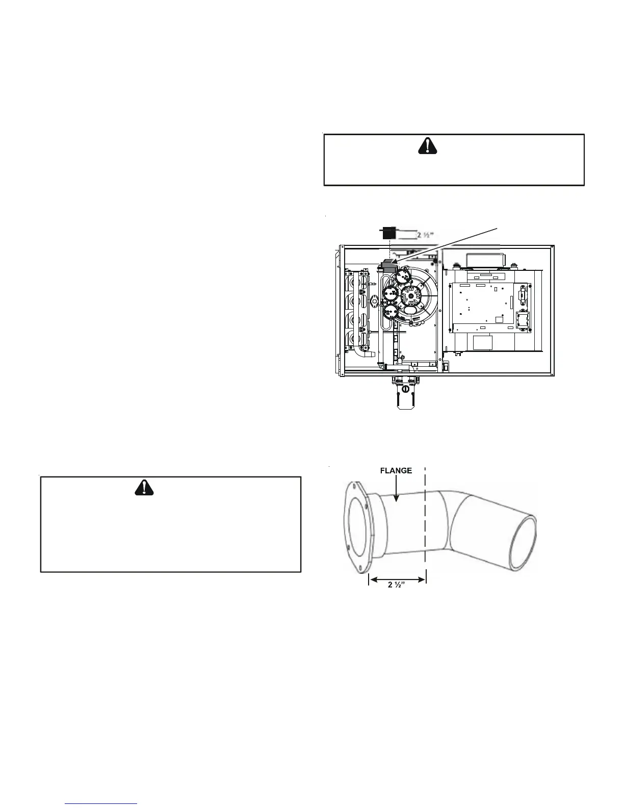
ALTERNATE VENT/FLUE LOCATION
The alternate vent/flue location is the large hole directly in line
with the induced draft blower outlet. To use the alternate vent/flue
location refer to the following steps and the “Alternate Vent/Flue
Location” figure. To use an alternate vent location on a
counterflow / horizontal model, a special kit is required.
NOTE: In the horizontal left installation position, a means of
condensate collection must be provided to keep vent pipe con-
densate from entering the draft inducer housing. If the vent
drain elbow is eliminated from the installation, an RF000142
kit must be used.
1. Remove the four screws from the vent pipe flange on top
the furnace.
2. Remove the internal elbow and vent pipe
3. Cut 2 1/2" from the flange .
4. Remove plastic plug in line with the inducer outlet
5. Install cut end of the flanged section and connect to inducer
with rubber coupling supplied with furnace.
6. Install screws removed in step 1 securing flange to cabinet.
ALTERNATE COMBUSTION AIR PROVISION
(Upflow / Horizontal models only)
When using the alternate venting location, either in a horizon-
tal left side down installation or a vertical installation using down – venting, an alternate combustion air opening can be
used. A locating dimple is located on the right side of the furnace cabinet. The locating dimple is 1 7/8" measured from the
front edge of the cabinet in line with the knock out. To use the alternate combustion air location:
1. Remove screws and combustion air flange from cabinet.
2. Insert cabinet plug in unused combustion air hole.
3. Drill a pilot hole at the cabinet dimple (size dictated by knockout tool used).
4. Use a knockout tool to create a 3" diameter hole
5. Install combustion air flange and secure with screws removed in step one.
E
DGES
OF
SHEET
METAL
HOLES
MAY
BE
SHARP
. U
SE
GLOVES
AS
A
PRECAUTION
WHEN
REMOVING
HOLE
PLUGS
.
WARNING
C
U
T
H
E
R
E
Figure 11
Vent/Flue Pipe Cuts
T
HE
RUBBER
ELBOW
IS
NOT
DESIGNED
TO
SUPPORT
A
LOAD
. W
HEN
THE
RUBBER
ELBOW
IS
MOUNTED
EXTERNALLY
TO
THE
FURNACE
CABINET
,
EXTREME
CARE
MUST
BE
TAKEN
TO
ADEQUATELY
SUPPORT
FIELD
-
SUPPLIED
VENT
/
FLUE
PIPING
,
AS
DAMAGE
CAN
RESULT
IN
LEAKS
CAUSING
BODILY
INJURY
OR
DEATH
DUE
TO
EXPOSURE
TO
FLUE
GASES
,
INCLUDING
CARBON
MONOXIDE
WARNING
Insert flange. Cut 2 ½” long.
Figure 10
RF000142