16
NON-DIRECT VENT (SINGLE PIPE) PIPING
Non-direct vent installations require only a vent/flue pipe. The
vent pipe can be run horizontally with an exit through the side of
the building or run vertically with an exit through the roof of the
building. The vent can also be run through an existing unused
chimney; however, it must extend a minimum of 12 inches above the top of the chimney. The space between the vent pipe and the
chimney must be closed with a weather-tight, corrosion-resistant flashing.
Although non-direct vent installations do not require a combustion air intake pipe, a minimum of one 90° elbow should be attached to
the furnace’s combustion air intake if: an upright installation uses the standard intake location, or a horizontal installation uses the
alternate air intake location. This elbow will guard against inadvertent blockage of the air intake.
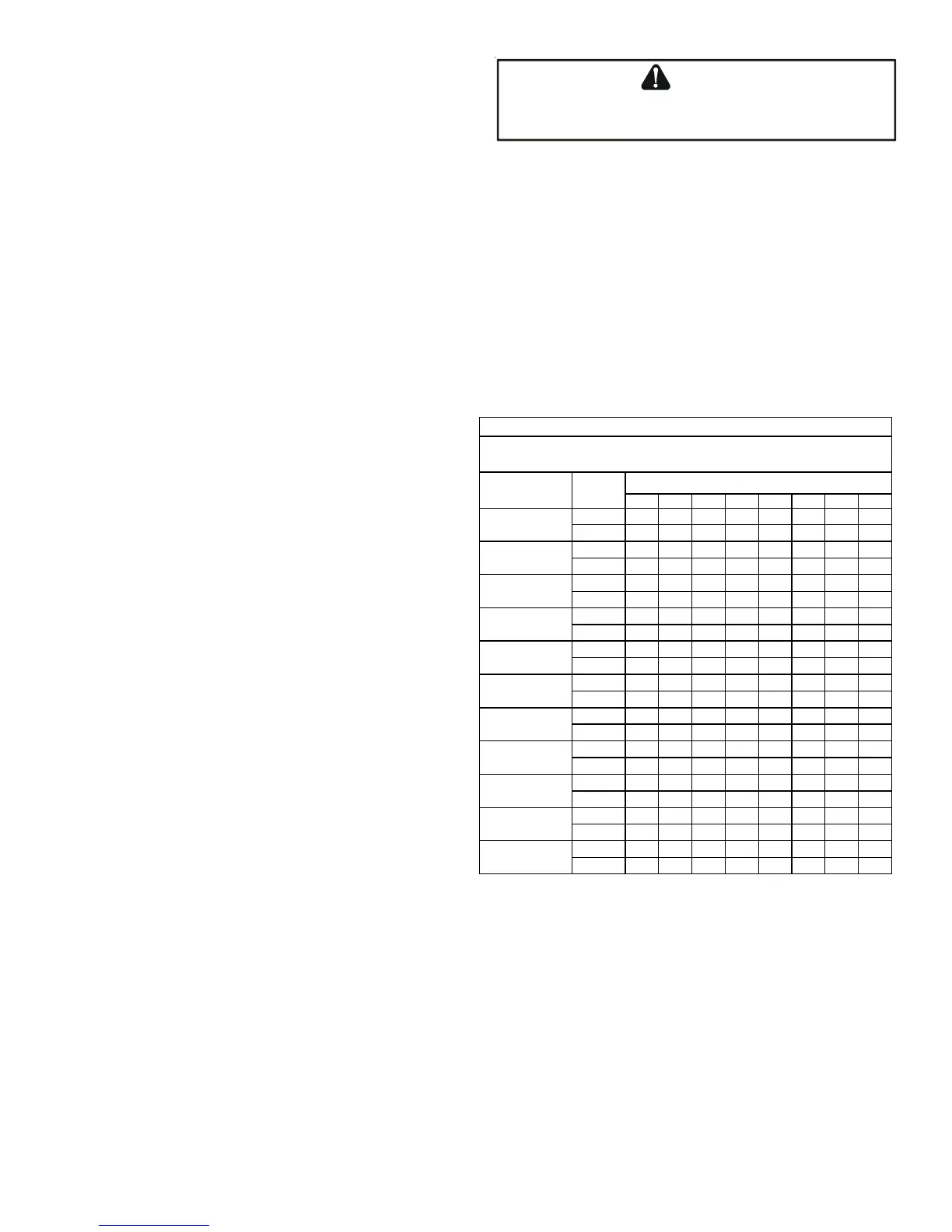
VENT/FLUE PIPE LENGTHS AND DIAMETERS
NOTE: If either a 90 degree or 45 degree elbow is used for termination, it must be pointed downward.
Refer to the following table for applicable length, elbows, and pipe diameter for construction of the vent/flue pipe system of a non-
direct vent installation. In addition to the vent/flue pipe, a single 90° elbow should be secured to the combustion air intake to prevent
inadvertent blockage. The tee used in the vent/flue termination must be included when determining the number of elbows in the
piping system.
1) Maximum allowable limits listed on individual lengths for
inlet and flue and NOT a combination.
2) Minimum requirement for each vent pipe is five (5) feet
in length and one elbow/tee.
3) Tee used in the vent/flue termination must be included
when determining the number of elbows in the piping sys-
tem
4) 2 1/2” or 3” diameter pipe can be used in place of 2”
diameter pipe.
5) Increased Clearance Configurations using (2) 45 deg.
Long Sweep elbows should be considered equivalent to one
90 deg. elbow.
6) One 90° elbow should be secured to the combustion air
intake connection.
VENT/FLUE PIPE TERMINATIONS
NOTE: If either a 90 degree or 45 degree elbow is used for
termination, it must be pointed downward.
The vent/flue pipe may terminate vertically, as through a roof,
or horizontally, as through an outside wall.
Vertical vent/flue pipe terminations should be as shown in the
following figure. Refer to Vent/Flue Pipe and Combustion Air Pipe - Termination Locations for details concerning location restrictions.
The penetration of the vent through the roof must be sealed tight with proper flashing such as is used with a plastic plumbing vent.
Horizontal vent/flue pipe terminations should be as shown in the following figure. Refer to Vent/Flue Pipe and Combustion Air Pipe.
To secure the pipe passing through the wall and prohibit damage to piping connections, a coupling should be installed on either side
of the wall and solvent cemented to a length of pipe connecting the two couplings. The length of pipe should be the wall thickness plus
the depth of the socket fittings to be installed on the inside and outside of the wall. The wall penetration should be sealed with
silicone caulking material.
B
E
SURE
NOT
TO
DAMAGE
INTERNAL
WIRING
OR
OTHER
COMPONENTS
WHEN
REINSTALLING
COUPLING
AND
SCREWS
.
CAUTION
12345678
2 120 115 110 105 100 95 90 85
3 134 127 120 113 106 99 92 85
2 100 95 90 85 80 75 70 65
3 151 144 137 130 123 116 109 102
2 4540353025201510
3 113106999285787164
2 706560555045N/AN/A
3 8982756861544740
2 N/AN/AN/AN/AN/AN/AN/AN/A
3 120 113 106 99 92 85 78 71
2 N/AN/AN/AN/AN/AN/AN/AN/A
3 151 144 137 130 123 116 109 102
2 120 115 110 105 100 95 N/A N/A
3 185 178 171 164 157 150 143 136
2 8580757065605550
3 168 161 154 147 140 133 126 119
2 40353025201510 5
3 120 113 106 99 92 85 78 71
2 N/AN/AN/AN/AN/AN/AN/AN/A
3 113106999285787164
2 N/AN/AN/AN/AN/AN/AN/AN/A
3 151 144 137 130 123 116 109 102
*M96VC/*C96VC Direct Vent (2 - Pipe) and Non-Direct Vent (1- Pipe)
(6)
Maximum Allowable Length of Vent/Flue Pipe
& Combustion Air Pipe (ft)
(1) (2)
Number of Elbows
(3) (5)
Pipe Size
(4)
(in.)
MODEL
DM96VC0403BN
DM96VC0603BN
DM96VC0803BN
DM96VC0804CN
DM96VC1005CN
DM96VC1205DN
DC96VC0403BN
DC96VC0603BN
DC96VC0804CN
DC96VC1005CN
DC96VC1205DN