38
2. While the furnace is operating at high fire rate, time and record one complete revolution of the gas meter dial, measuring
the smallest quantity, usually the dial that indicates 1/2 cu. ft. per revolution. You will use this number to calculate
the quantity of gas in cubic ft. if the furnace would consume if it ran steadily for one hour (3600 seconds).
3. If the 1/2 cu. ft. dial was used, multiply your number x 2.
EXAMPLE: If it took 23 seconds to complete one revolution of the 1/2 ft. dial (23 x 2 = 46).
This tells us that at this rate, it would take 46 seconds to consume one cu. ft. of gas. 3600 / 46 = 78.
This tells us that in one hour, the furnace would consume 78 cu. ft. of gas.
The typical value range for 1 cu. ft. of natural gas is around 1000 BTU. Check with your gas utility, if possible. In this
example, the furnace is consuming 78,000 BTUH.
NOTE: The final manifold pressure cannot vary by more than ± 0.3” w.c. for Natural and + 0.5” for LP from the specified
setting. Consult your local gas supplier if additional input rate adjustment is required.
4. Turn ON gas to and relight all other appliances turned off in step 1. Be certain that all appliances are functioning properly and
that all pilot burners are operating.
TEMPERATURE RISE
Temperature rise must be within the range specified on the unit rating plate. An incorrect temperature rise may result in condensing
in or overheating of the heat exchanger. An airflow and temperature rise table is provided in the Specification Sheet applicable to
your model. Determine and adjust temperature rise as follows:
1. Operate furnace with burners firing for approximately ten minutes. Ensure all registers are open and all duct dampers are in
their final (fully or partially open) position.
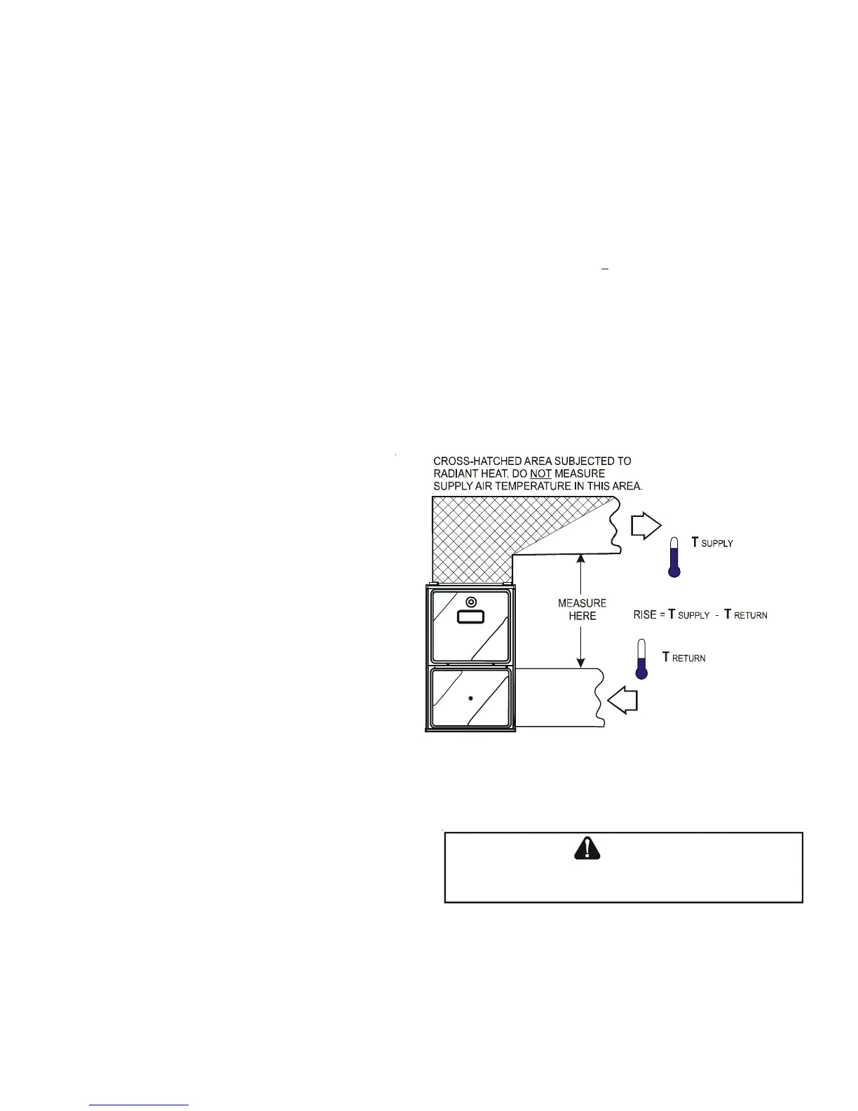
2. Place thermometers in the return and supply ducts as
close to the furnace as possible. Thermometers must
not be influenced by radiant heat by being able to
“see” the heat exchanger.
3. Subtract the return air temperature from the supply
air temperature to determine the air temperature
rise. Allow adequate time for thermometer readings
to stabilize.
4. Adjust temperature rise by adjusting the circulator
blower speed. Increase blower speed to reduce
temperature rise. Decrease blower speed to increase
temperature rise. Refer to Startup Procedure and
Adjustment -Circulator Blower Speeds for speed
changing details.
CIRCULATOR BLOWER SPEEDS
This furnace is equipped with a variable speed circulator
blower. This blower provides ease in adjusting blower
speeds. The heating blower speed is shipped set at “B”,
and the cooling blower speed is set at “D”. These blower speeds
should be adjusted by the installer to match the installation re-
quirements so as to provide the correct heating temperature rise
and correct cooling CFM.
Use the dual 7-segment LED display adjacent to the dip switches
to obtain the approximate airflow quantity. The airflow quantity
is displayed as a number on the display, rounded to the nearest 100 CFM. The display alternates airflow delivery indication and the
operating mode indication.
Example: The airflow being delivered is 1225 CFM. The display indicates 12. If the airflow being delivered is 1275, the display
indicates 13.
1. Determine the tonnage of the cooling system installed with the furnace. If the cooling capacity is in BTU/hr divide it by 12,000
to convert capacity to tons.
SUPPLY
AIR
RETURN
AIR
Temperature Rise Measurement
Figure 48
T
O
AVOID
PERSONAL
INJURY
OR
DEATH
DUE
TO
ELECTRICAL
SHOCK
,
TURN
OFF
POWER
TO
THE
FURNACE
BEFORE
CHANGING
SPEED
TAPS
.
WARNING