22
COUNTERFLOW MODEL INSTALLED VERTICALLY
The furnace drain may exit the right or left side of the furnace cabi-
net (left side preferred) Trap and factory installed hoses remain as
shipped if the drain will exit the left side of the cabinet. Draining
from the right side requires re-location of the trap to outside the
cabinet.
DRAIN EXITING LEFT SIDE
1. Install a field supplied rubber coupling secured with a 1 1/4”
clamp to enable removing the trap for future cleaning. Alternately,
a PVC fitting may be glued on the trap outlet.
2. Install drain per local and National codes.
DRAIN EXITING RIGHT SIDE
1. Remove hose clamps and hoses from trap.
2. Remove trap.
3. (Draining the Vent Elbow) Insert the non-grommet end hose #10
into the cabinet back drain hole. Secure on vent – drain elbow
barb fitting with a red clamp.
4. Insert 100º elbow into the cut end and secure with red clamp.
5. (Draining the Collector Box) Insert non-grommet end of hose
#9 into the cabinet front drain hole and secure on collector
box drain port with a silver clamp.
6. Mate the drain trap inlets to the hoses and secure with silver
clamps.
7. Line up the trap mounting holes with the pre-drilled holes in
the furnace and secure with 2 screws removed in step 2.
8. Refer to Field Supplied Drain section for instructions on field
supplied / installed drain on outlet of furnace trap.
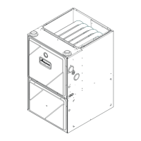
COUNTERFLOW MODEL INSTALLED HORIZONTALLY WITH RIGHT
SIDE DOWN
Minimum 5 ½" clearance is required for the drain trap beneath
the furnace.
*Also see Front Cover Pressure Swith Tube Location on page
10
1. Remove hose clamps and hoses from trap.
2. Remove trap.
3. (Draining the Collector Box) From outside the cabinet,
insert the non-grommet end hose #8 into the back drain
hole.
4. Secure to collector box drain port using a silver clamp.
5. (Draining the Vent Elbow) From outside the cabinet, insert
the non-grommet end of hose #7 into the front cabinet
drain hole and secure on the vent – drain elbow barb fitting
using a red clamp
6. Mate the trap inlets to the hoses, the outlet of the trap
must face the original bottom of the furnace. Secure with
silver clamps.
7. Fasten the drain trap to the cabinet with two screws
removed in step 2
8. Refer to Field Supplied Drain section for instructions on field supplied / installed drain on outlet of furnace trap.
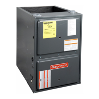
Hose #5 x 2
Hose #4 x 2
Figure 25
Drain Port
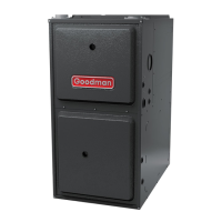
Hose #7
Hose #8
Figure 27