17
NOTE: Terminate both pipes in the same pressure zone (same side of roof, no major obstacles between pipes, etc.).
STRAIGHT
ELBOWS
Figure 14
F
l
o
o
r
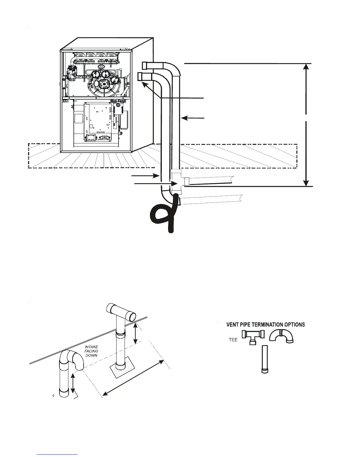
Use alternate vent
& combination air locations
DOWN VENTING UPFLOW MODEL FURNACES ONLY
B
a
s
e
m
e
n
t
/
C
r
a
w
l
s
p
a
c
e
Condensate trapped
to prevent flue gas from escaping
and routed to field supplied
condensate disposal
Combustion Air Pipe
Vent Pipe
All piping and fittings must be joined per material manufacturer’s specifications
to prevent separation and flue gas leaks.
Both Pipes Terminated
Outside Structure
1/4” per foot min. slope
6’ MAX.
Field Supplied
Drain Tee on Vent Pipe
Figure 12
COMBUSTION AIR INTAKE
(OPTIONAL)
*Not required for
single pipe installation
TEE (OPTIONAL)
9
6
”
M
A
X
.
-
3
”
M
I
N
.
R
O
O
F
L
I
N
E
12” MIN
HEIGHT DIFFERENCE
BETWEEN
INTAKE AND VENT
12” MIN TO ROOF OR HIGHEST
ANTICIPATED SNOW LEVEL
Figures 13