18
DIRECT VENT (DUAL PIPE) PIPING
Direct vent installations require both a combustion air intake and a vent/
flue pipe. The pipes may be run horizontally and exit through the side of the
building or run vertically and exit through the roof of the building. The
pipes may be run through an existing unused chimney; however, they must
extend a minimum of 12 inches above the top of the chimney. The space
between the pipes and the chimney must be closed with a weather tight,
corrosion resistant flashing. Both the combustion air intake and a vent/
flue pipe terminations must be in the same atmospheric pressure zone.
Refer to Vent/Flue and Combustion Air Pipe - Termination Locations or
Concentric Vent Termination for specific details on termination construc-
tion. For details concerning connection of pipes to the furnace, refer to the
Vent/Flue Pipe and Combustion Pipe - Standard Furnace Connections or
Alternate Furnace Connections.
VENT/FLUE & COMBUSTION AIR PIPE LENGTHS & DIAMETERS
Refer to the following table for applicable length, elbows, and pipe di-
ameter for construction of the vent/flue and combustion air intake
pipe systems of a direct vent (dual pipe) installation. The number of
elbows tabulated represents the number of elbows and/or tees in each
(Vent/Flue & Combustion Air Intake) pipe. Elbows and/or tees used in
the terminations must be included when determining the number of
elbows in the piping systems.
If the combustion air intake pipe is to be installed above a finished ceiling or
other area where dripping of condensate will be objectionable, insulation of
the combustion air pipe may be required. Use 1/2” thick closed cell foam
insulation such as Armaflex™ or Insultube™ where required.
VENT/FLUE AND COMBUSTION AIR PIPE TERMINATIONS
The vent/flue and combustion air pipes may terminate vertically, as through
a roof, or horizontally, as through an outside wall.
Vertical pipe terminations should be as shown in the following figure. Refer to Vent/Flue Pipe and Combustion Pipe - Termination
Locations for details concerning location restrictions. The penetrations through the roof must be sealed tight with proper flashing
such as is used with a plastic plumbing vent.
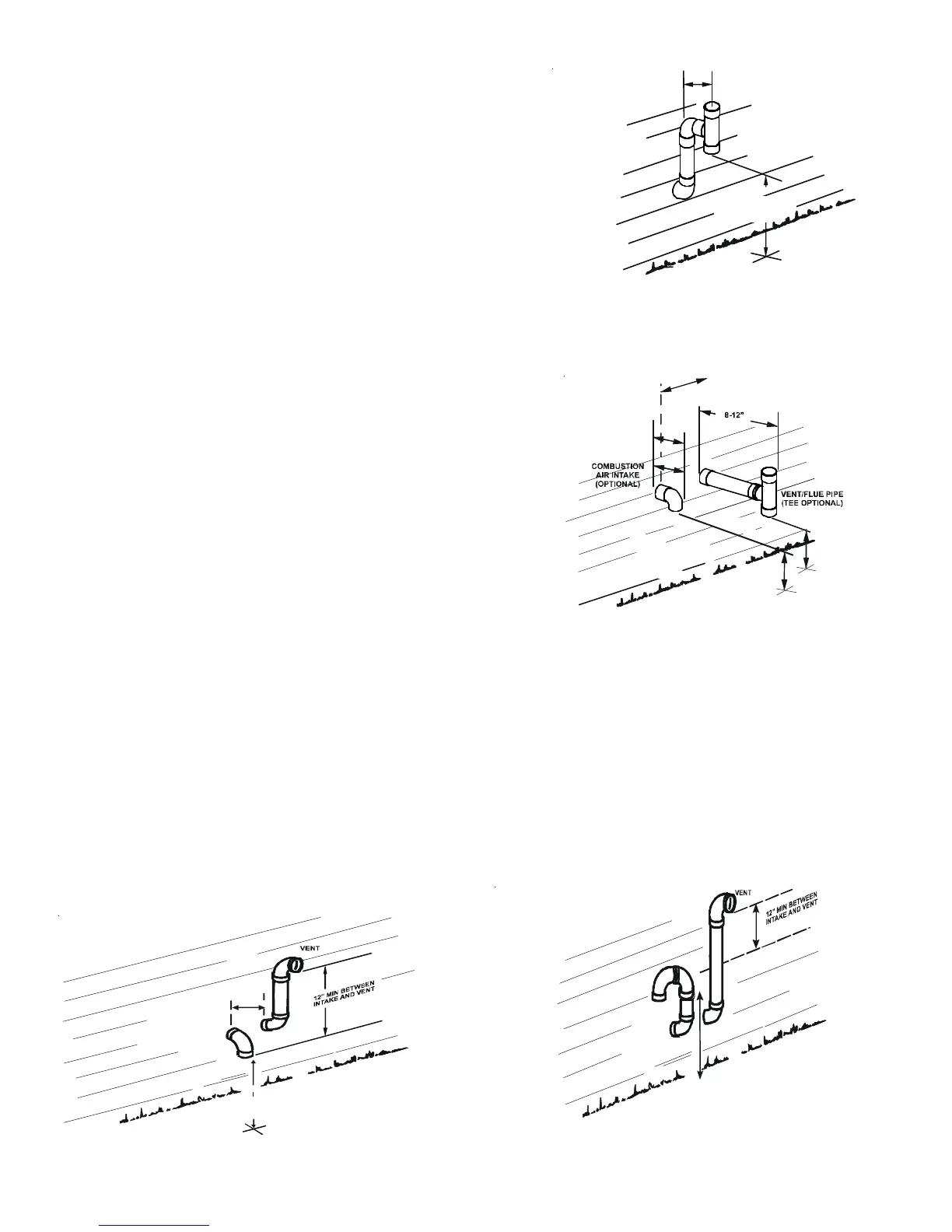
VENT & COMBUSTION AIR INTAKE MEASUREMENTS FOR STANDARD HORIZONTAL TERMINATIONS (DUAL PIPE)
Center to center = 10” min / 24” max.
Vertical separation: 0” - 24”
Vent termination from wall = 8” min / 12” max.
Combustion air intake from wall = 6” max.
Combustion Air Intake may also be snorkeled to obtain 12” min ground clearance.
Alternate Vent Termination Above Anticipated Snow Level
(Dual Pipe)
Figure 18
90°
ELBOWS
12" MIN. ABOVE
HIGHEST ANTICIPATED
SNOW LEVEL
3”-24” BETWEEN PIPES
90º OR 45°
ELBOW
12" MIN. TO GRADE OR
HIGHEST ANTICIPATED
SNOW LEVEL
6” MAX
4” MIN
Standard Horizontal Terminations (Dual Pipe)
Figure 16
12" MIN. ABOVE
HIGHEST ANTICIPATED
SNOW LEVEL
12" MIN.
ENT/FLUE TEE (
or
45° ELBOW
TURNED DOWN or
90° ELBOW TURNED
DOWN
OPTIONAL)
Horizontal Termination (Single Pipe)
Above Highest Anticipated Snow Level
Figure 15
Alternate Horizontal Vent Termination (Dual Pipe)
Figure 17
90°
ELBOWS
12" MIN. ABOVE
HIGHEST ANTICIPATED
SNOW LEVEL
3” - 24”