SERVICING
30
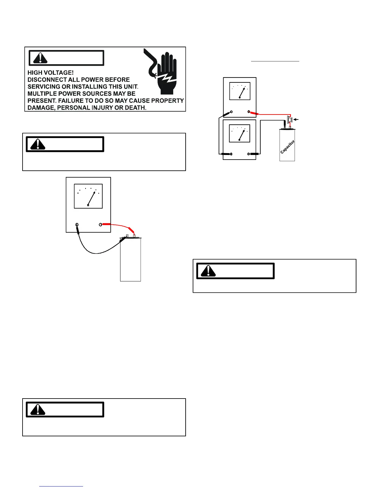
S-15A RESISTANCE CHECK
WARNING
1. Discharge capacitor and remove wire leads.
WARNING
DISCHARGE CAPACITOR THROUGH A 20 TO 30 OHM
RESISTOR BEFORE HANDLING.
Cap
a
cito
r
Volt / Ohm
Meter
TESTING CAPACITOR RESISTANCE
2. Set an ohmmeter on its highest ohm scale and connect
the leads to the capacitor -
A. Good Condition - indicator swings to zero and slowly
returns to infinity. (Start capacitor will bleed resistor will
not return to infinity. It will still read the resistance of the
resistor).
B. Shorted - indicator swings to zero and stops there -
replace.
C. Open - no reading - replace. (Start capacitor would read
resistor resistance).
S-15B CAPACITANCE CHECK
WARNING
DISCHARGE CAPACITOR THROUGH A 20 TO 30 OHM
RESISTOR BEFORE HANDLING.
Using a hookup as shown below, take the amperage and volt-
age readings and use them in the formula:
Capacitance (MFD) =
2650 X Amperage
Voltage
15 AMP FUSE
Volt / Ohm
Meter
AMMETER
TESTING CAPACITANCE
S-16 CHECKING MOTORS
S-16A CHECKING FAN AND BLOWER MOTOR
WINDINGS (PSC MOTORS)
The auto reset fan motor overload is designed to protect the
motor against high temperature and high amperage conditions
by breaking the common circuit within the motor, similar to the
compressor internal overload. However, heat generated within
the motor is faster to dissipate than the compressor, allow at
least 45 minutes for the overload to reset, then retest.
WARNING
DISCONNECT POWER SUPPLY BEFORE SERVICING.
1. Remove the motor leads from its respective connection
points and capacitor (if applicable).
2. Check the continuity between each of the motor leads.
3. Touch one probe of the ohmmeter to an unpainted end of
the motor frame (ground) and the other probe in turn to
each lead.
If the windings do not test continuous or a reading is obtained
from any lead to ground, replace the motor.
S-16D CHECKING GE X13
TM
MOTORS
The GE X13
TM
Motor is a one piece, fully encapsulated, 3 phase
brushless DC (single phase AC input) motor with ball bearing
construction. Unlike the ECM 2.3/2.5 motors, the GE X13
TM
features an integral control module.
Note: The GE TECMate will not currently operate the GE X13
TM
motor.
1. Using a voltmeter, check for 230 volts to the motor connec-
tions L and N. If 230 volts is present, proceed to step 2. If
230 volts is not present, check the line voltage circuit to
the motor.