SERVICING
36
5. With the system still running, reseat the suction valve core,
remove hose and reinstall both valve core caps.
6. Check system for leaks.
Units having flow control restrictors can be checked against
the Desired Superheat vs. Outdoor Temperature Chart in this
section.
S-104 CHECKING COMPRESSOR
EFFICIENCY
The reason for compressor inefficiency is broken or damaged
suction and/or discharge valves, or scroll flanks on Scroll com-
pressors, reducing the ability of the compressor to pump re-
frigerant vapor.
The condition of the valves or scroll flanks is checked in the
following manner.
1. Attach gauges to the high and low side of the system.
2. Start the system and run a Cooling Performance Test.
If the test shows-
⇒ Below normal high side pressure.
⇒ Above normal low side pressure.
⇒ Low temperature difference across coil.
⇒ Low amp draw at compressor.
-and the charge is correct. The compressor is faulty - replace
the compressor.
S-108 SUPERHEAT
CHECKING SUPERHEAT
Refrigerant gas is considered superheated whenever its tem-
perature is higher than the saturation temperature correspond-
ing to its pressure. The degree of superheat equals the de-
grees of temperature increase above the saturation tempera-
ture at existing pressure. See Temperature - Pressure Chart.
1. Attach an accurate thermometer or preferably a thermo-
couple type temperature tester to the suction line at a point
at least 6" from the compressor.
2. Install a low side pressure gauge on the suction line ser-
vice valve at the outdoor unit.
3. Record the gauge pressure and the temperature of the line.
4. Convert the suction pressure gauge reading to temperature
by finding the gauge reading in Temperature - Pressure
Chart and reading to the left, find the temperature in the °F.
Column.
5. The difference between the thermometer reading and pres-
sure to temperature conversion is the amount of super-
heat.
EXAMPLE:
a. Suction Pressure = 84
b. Corresponding Temp. °F. = 50
c. Thermometer on Suction Line = 63°F.
To obtain the degrees temperature of superheat subtract 50.0
from 63.0°F.
The difference is 13° Superheat.
For charging in the warmer months, 10°F superheat at the
compressor is required at conditions: 95°F outdoor ambient
(dry bulb temperature), 80°F dry bulb / 67°F wet bulb indoor
ambient, approximately 50 % humidity. This superheat varies
when conditions vary from the conditions described.
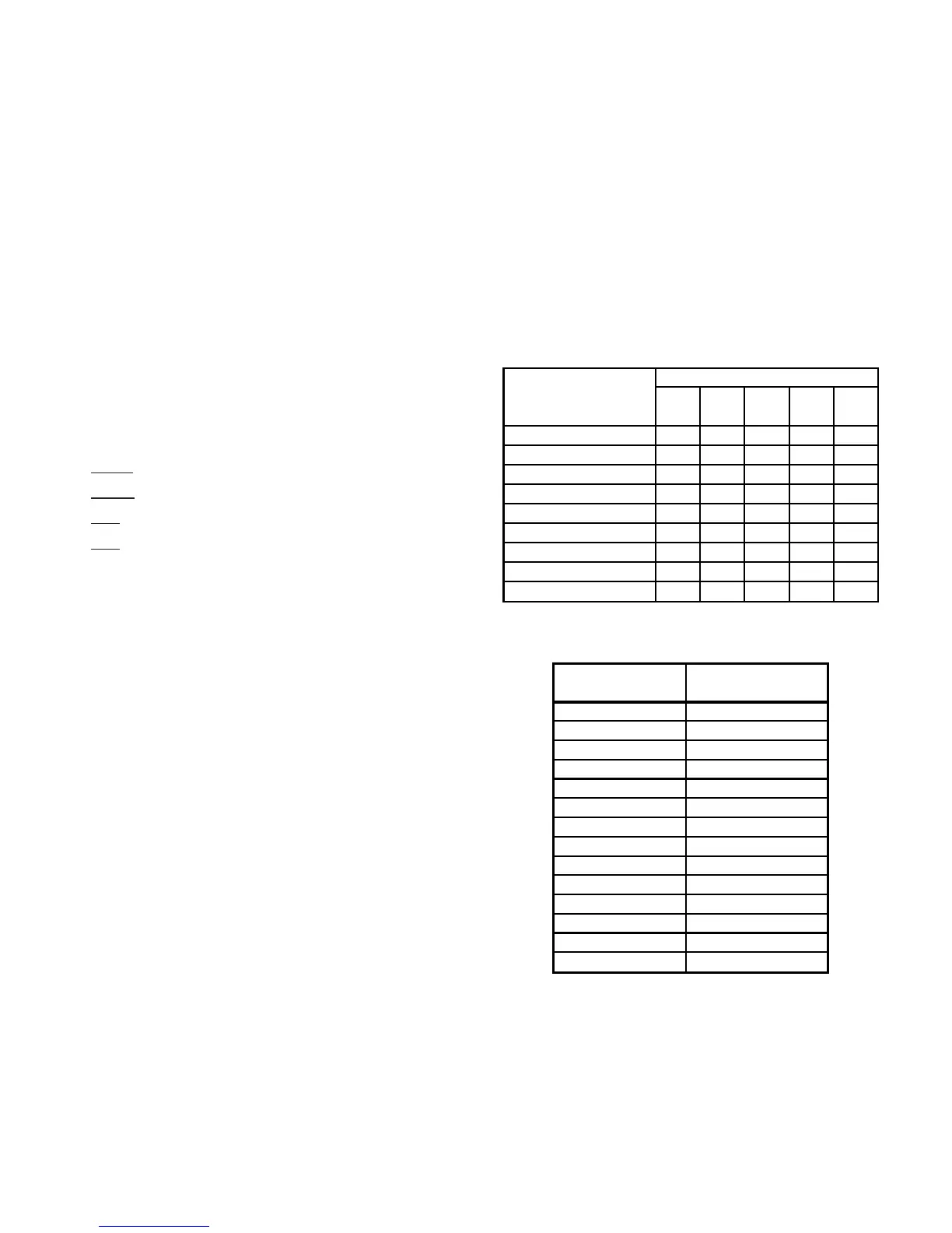
A superheat charge chart is provided below for other operating
conditions. Use it to provide the correct superheat at the
conditions the unit is being charged at.
After superheat is adjusted it is recommended to check unit
sub-cooling at the condenser coil liquid line out.
100 - - - 10 10
95
- - 10 10 10
90
- - 12 15 18
85
- 10 13 17 20
80
- 10 15 21 26
75 10 13 17 25 29
70 10 17 20 28 32
65 13 19 26 32 35
60 17 25 30 33 37
Ambient Condenser
Inlet Temp (°F
Drybulb)
65 70 75
Return Air Temp. (°F Drybulb)
80 85
Superheat
Suction Pressure
a
ura
e
uc
on
Temperature (°F)
50 26
53 28
55 30
58 32
61 34
63 36
66 38
69 40
72 42
75 44
78 46
81 48
84 50
87 52
TABLE 5
Suction Pressure Temperature (R-22)
S-109 CHECKING SUBCOOLING
Refrigerant liquid is considered subcooled whenever its tem-
perature is lower than the saturation temperature correspond-
ing to its pressure. The degree of subcooling equals the de-
grees of temperature decrease below the saturation tempera-
ture at the existing pressure.