SERVICING
35
WARNING
SCROLL COMPRESSORS
DO NOT FRONT SEAT THE SERVICE VALVE(S) WITH
THE COMPRESSOR OPERATING IN AN ATTEMPT TO
SAVE REFRIGERANT. WITH THE SUCTION LINE OF
THE COMPRESSOR CLOSED OR SEVERLY RESTRICT-
ED, THE SCROLL COMPRESSOR WILL DRAW A DEEP
VACUUM VERY QUICKLY. THIS VACUUM CAN CAUSE
INTERNAL ARCING OF THE FUSITE RESULTING IN A
DAMAGED OR FAILED COMPRESSOR.
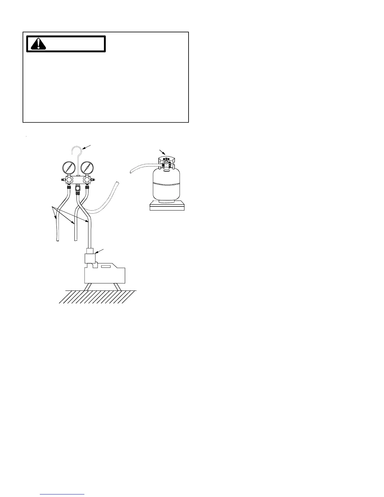
LOW SIDE
GAUGE
AND VALVE
HIGH SIDE
GAUGE
AND VALVE
TO
UNIT SERVICE
VALVE PORTS
VACUUM PUMP
VACUUM PUMP
ADAPTER
800 PSI
RATED
HOSES
CHARGING
CYLINDER
AND SCALE
{
R-22
MANIFOLD
1. Connect the vacuum pump, vacuum tight manifold set with
high vacuum hoses, thermocouple vacuum gauge and charg-
ing cylinder as shown.
2. If the service dill valves are to be used for evacuation, it is
recommended that a core remover be used to lift the core
for greater efficiency.
3. Start the vacuum pump and open the shut off valve to the
high vacuum gauge manifold only. After the compound
gauge (low side) has dropped to approximately 29 inches
of vacuum, open the valve to the vacuum thermocouple
gauge. See that the vacuum pump will blank-off to a maxi-
mum of 25 microns. A high vacuum pump can only pro-
duce a good vacuum if its oil is non-contaminated.
4. If the vacuum pump is working properly, close the valve to
the vacuum thermocouple gauge and open the high and
low side valves to the high vacuum manifold set. With the
valve on the charging cylinder closed, open the manifold
valve to the cylinder.
5. Evacuate the system to at least 29 inches gauge before
opening valve to thermocouple vacuum gauge.
6. Continue to evacuate to a minimum of 250 microns. Close
valve to vacuum pump and watch rate of rise. If vacuum
does not rise above 1500 microns in three to five minutes,
system can be considered properly evacuated.
7. If thermocouple vacuum gauge continues to rise and levels
off at about 5000 microns, moisture and non-condensables
are still present. If gauge continues to rise a leak is present.
Repair and re-evacuate.
8. Close valve to thermocouple vacuum gauge and vacuum
pump. Shut off pump and prepare to charge.
S-103 CHARGING
Charge the system with the exact amount of refrigerant.
Refer to the specification section or check the unit nameplates
for the correct refrigerant charge.
After completing airflow measurements and adjustments, the
unit’s refrigerant charge must be checked. The unit comes
factory charged, but this charge is based on 400 CFM per ton
at minimum ESP per ARI test conditions (generally between
.15 - .25 ESP). When air quantity or ESP is different than
above, charge must be adjusted to the proper amount.
All package units are charged to the superheat method at the
compressor suction line (these are fixed orifice devices).
For charging in the warmer months, 10
0
F superheat at the com-
pressor is required at conditions: 95
0
F outdoor ambient (dry
bulb temperature), 80
0
F dry bulb / 67
0
F wet bulb indoor ambi-
ent, approximately 50% humidity. This superheat varies when
conditions vary from the conditions described.
A superheat charge chart is available for other operating condi-
tions. Use it to provide the correct superheat at the conditions
the unit is being charged at.
After superheat is adjusted it is recommended to check unit
sub-cooling at the condenser coil liquid line out. In most oper-
ating conditions 10 - 15
0
F of sub-cooling is adequate.
An inaccurately charged system will cause future problems.
1. Using a charging scale, allow liquid refrigerant only to enter
the high side.
2. After the system will take all it will take, close the valve on
the high side of the charging manifold.
3. Start the system and charge the balance of the refrigerant
through the low side. DO NOT charge in a liquid form.
4. With the system still running, close the valve on the charg-
ing manifold. At this time, you may still have some liquid
refrigerant in the charging manifold and will definitely have
liquid in the liquid hose. Reseat the liquid line core. Slowly
open the high side manifold valve and transfer the liquid
refrigerant from the liquid line hose and charging manifold
into the suction service valve port. CAREFUL: Watch so
that liquid refrigerant does not enter the compressor.