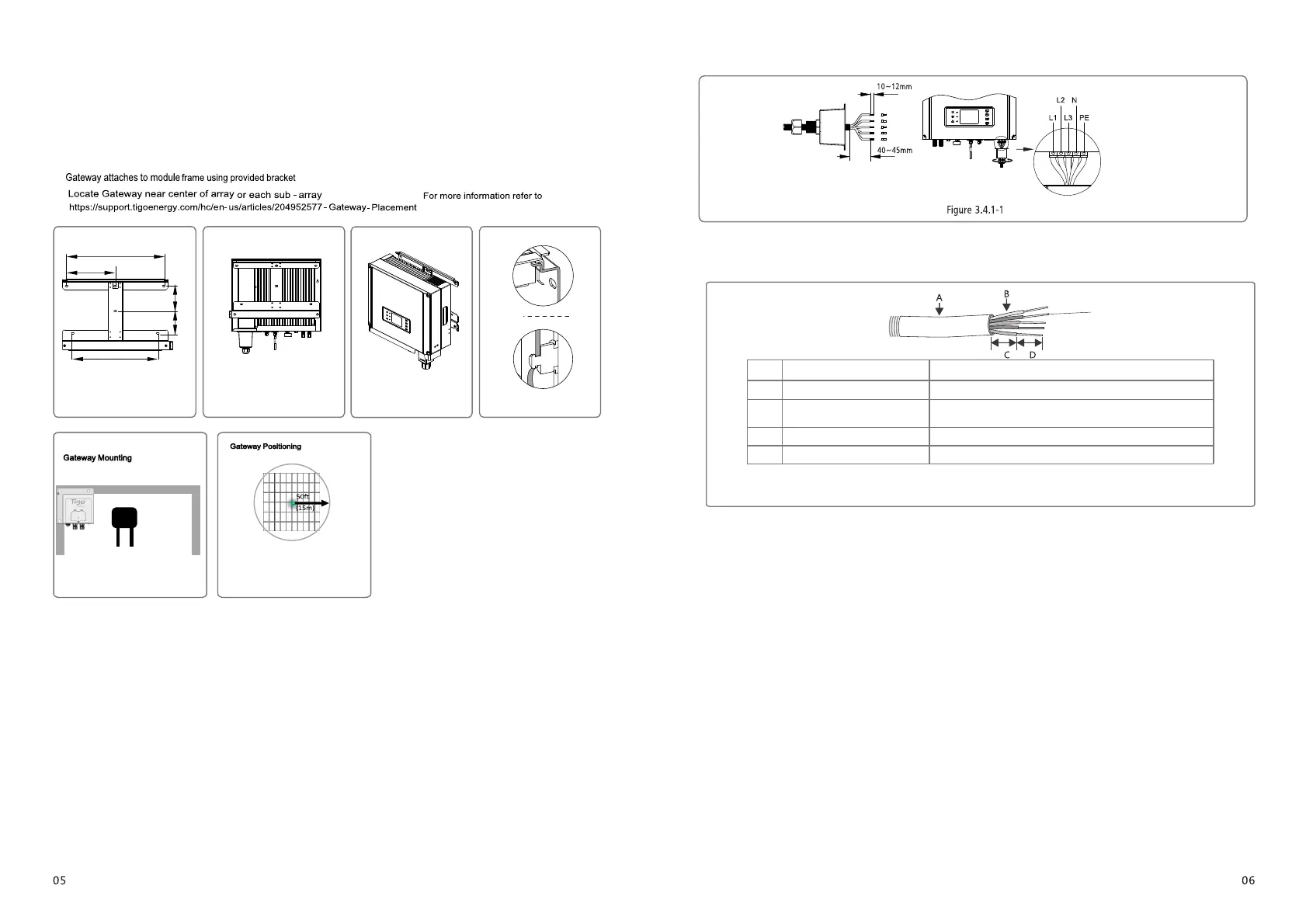
(7) Fix (Torque: 2~2.5 N.m) the connector of AC cable to the corresponding terminals.
(8) Neutral conductor shall be blue, line conductor shall be black or brown (preferred), protective earth bonding line shall be yellow-green.
(9) The AC line construction shall be such that if the cord should slip in its anchorage, placing a strain on conductors, the
protective earthing conductor will be the last to take the strain. such as the PE line is longer than L and N.
(1) Use the wall-mounted bracket as a template and drill 6 holes on the wall, 10 mm in diameter and 80 mm deep.
The size of SDT series refer to Figure 3.3.2-1.
(2) Fix the wall mounting bracket on the wall with six expansion bolts in accessory bag.
(3) Hold the inverter by the groove on it.
(4) Place the inverter on the wall-mounted bracket as illustrated in Figure 3.3.2-2、3.3.2-3.
3.3.2 Mounting Procedure
Figure 3.3.2-1 Figure 3.3.2-2
457
228.5
400
117.5
104.5
Figure 3.3.2-3 Figure 3.3.2-4
3.4 Electrical Connection
3.4.1 Connection to Grid (AC Side Connection)
(1) Check the grid voltage and frequency, select a suitable safety standard from inverter that comply with this requirements.
(2) Add breaker or fuse to AC side, the specification should be more than 1.25 times of rated AC output current.
(3) The PE line of inverter should be connected to the earth, make sure the impedance of neutral wire and earth wire less than 10 ohm.
(4) Disconnect the breaker or fuse between the inverter and the utility.
(5) The integrated leakage current detection device of the inverter can detect external leakage current in real time. When the detected
leakage current exceeds the limit value, inverter will quickly disconnect with the grid. If the leakage current protection device is
installed externally, the action current should be 300mA or higher.
(6) Connect the inverter to the grid as follows:
Installation instruction of waterproof coupling series connector please refer to Figure 3.4.1-1.
wire crimpers impose line
L1 ----- 1
L2 ----- Live Wire 2
L3 ----- Live Wire 3
N ------ Neutral Wire
PE------ Earth Wire
Live Wire
fasten screw cap clockwise
Ensure the wire be locked tightly
Note: TheNlineofGW30K-DTshouldnot beconnected.
AC cable illustration please refer to Figure 3.4.1-2.
Annealed copper wire
Grade Description
A O.D.
B
C
D
Bare Wire Length
Wire Length
Copper Conductor Material
Sectional Area*
Value
SDT: 4~10kW: 11~23mm
SDT: 4~10kW: 4~10mm²
45mm around
12mm around
Figure 3.4.1-2
Figure 3.3.2-5
Figure 3.3.2-6
(5)
refer to Figure 3.3.2-5.
(6)
.
refer to Figure 3.3.2-6.
.
 Loading...