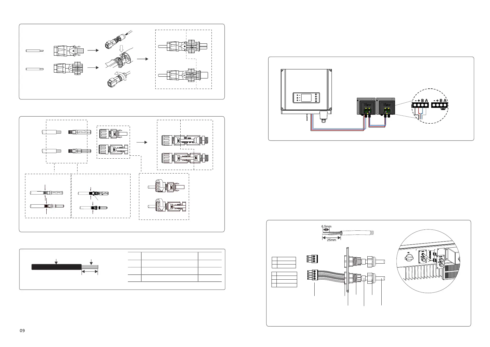
Inverter
Positive connector
Negative connector
Figure 3.4.3-1
Negative connector
Positive connector
Inverter
Special tools are used to stitching
Note: For installation of Amphenol connectors, These two limit buckles of Amphenol connectors are only for
installation positioning use, can’t crimp the wire.
MC4 series
AMPHENOL series
Figure 3.4.3-2
Limit buckle can’t
crimp the wire
DC Cable specification please refer to Figure 3.4.3-3.
Value
4~5mm
2.5~4mm²
7mm around
Grade Description
A O.D.
B Conductor Material Sectional Area
C Bare Wire Length
Figure 3.4.3-3
A
B
C
*DC Cable should be use dedicated PV cable.
(1) Gateway communication connection procedure:
●Remove the waterproof kit of gateway cover with screwdriver.
●Remove the screw cap of the cable gland.
●Remove the one-hole sealing ring.
●Insert the gateway cable through the components as the followings: screw cap, one-hole sealing ring, insulation body and sheet
metal parts.
●Fasten the cable as Figure shown, figure 3.4.4-2.
●Connect the compressed cable to the bulit-in communication interface of inverter.
●Fasten the gateway waterproof kit to inverter.
●Fasten the screw cap of the cable gland.
INVERTER
Figure 3.4.4-1
3.4.4 Gateway connect
The gateway port connects to tigo’s gateway port. Port1 connects to A, Port2 connects to B, Port3 connects to +, Port4
connects to -.
Gateway connection please refer to Figure 3.4.4-1.
10
SDT4~10KW
RS485
Communication
Board
Screw cap
Single hole
seal ring
The
insulator
Nut
Cables
Screw
1 2 3
1 2 3 4
Figure 3.4.4-2
1
2 485A
3 485B
GND_COM
1 A (gateway)
2 B (gateway)
3 + (gateway)
4 - (gateway)
 Loading...