31
06 Electrical Connection
User Manual V1.6-2024-03-20
ON-GRID
BACK-UP
BAT
PV
Meter
E-N Link
N-BAR
E-BAR
or
L3
N
PE
BMS
CT1
L1
L1 L2
L3
N
N
PE
PE
L1
CT2
L2
L2
CT3
L3
L3
N
PE
L3
L2
L2
L1
L1
N
PE
PE
6 Electrical Connection
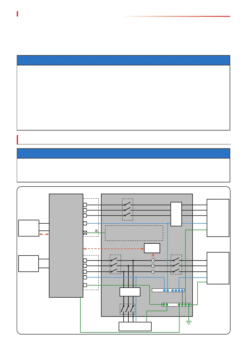
6.1 System Wiring Diagram
NOTICE
• N and PE wiring via ON-GRID and BACK-UP ports of the inverter are dierent based on the
regulation requirements of dierent regions. Refer to the specic requirements of local
regulations.
• There are built-in relays inside of the inverter’s ON-GRID and BACK-UP AC ports. When the
inverter is in the o-grid mode, the built-in ON-GRID relay is open; while when the inverter
is in grid-tied mode, it is closed.
• When the inverter is powered on, the BACK-UP AC port is charged. Power o the inverter
rst if maintenance is required for the loads connected with BACK-UP ports. Otherwise, it
may cause electric shock.
NOTICE
• To maintain neutral integrity, the neutral cable of ON-GRID side and BACK-UP side must be
connected together, otherwise BACK-UP function will not work.
• The following diagram is applicable to areas in Australia, New Zealand, etc.
BACK-UP
Loads
Smart
Meter
Utility grid
Normal loads
Battery
PV string
RCD
RCD
Do not wire in this position
if N and PE cables are
connected together.
N and PE cables are connected together in the Main Panel for wiring.
Inverter Main panel