- 10 - B.6.20.44-B
F22.060.02, issued on 01.98
FLUID PRESSURE SYSTEM
The fluid pressure system usually consists of a high-pressure screen, a hose line and a spray
gun or atomizer.
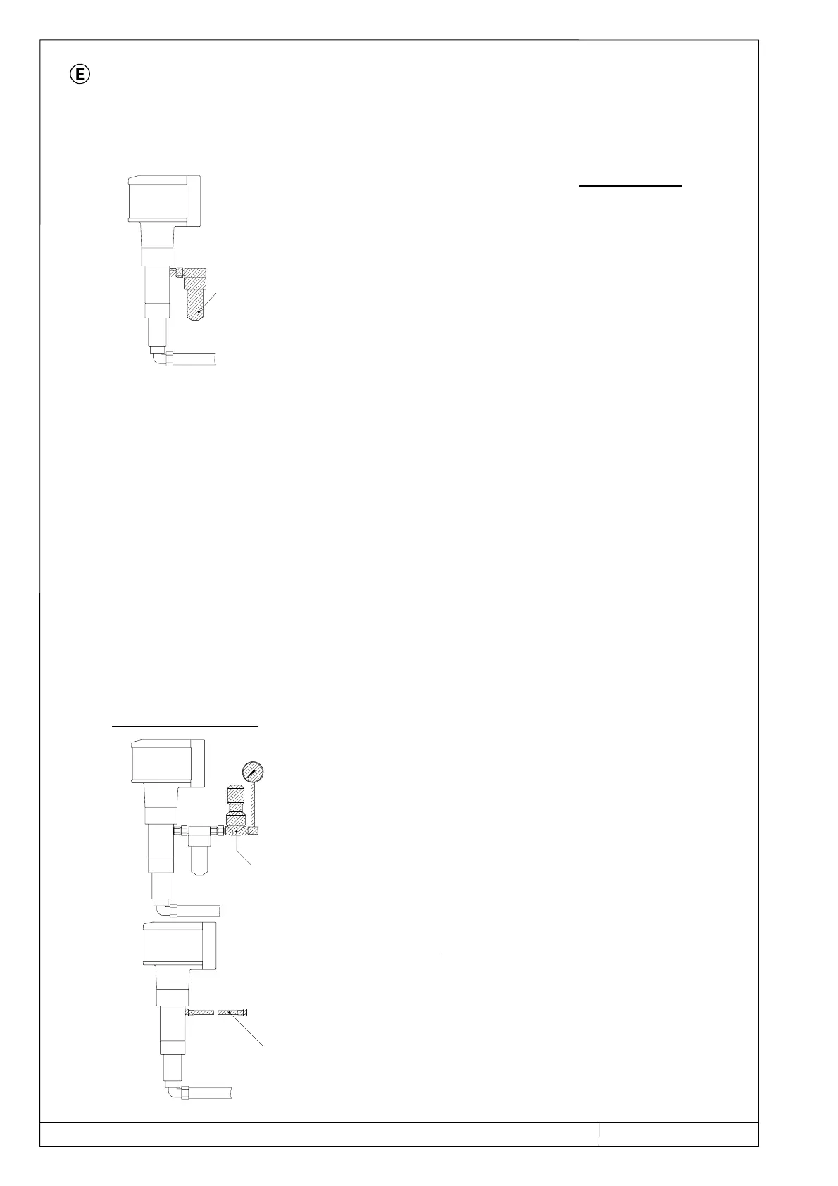
In most reciprocating pumps, the screen PN 500 is fitted
at the factory and tested together with the reciprocating
pump (final testing of the pump).
The screen consists of the housing parts, the screen
insert and a pressure relief device (drain plug).
The connection sieve
↔
reciprocating pump is effected
by means of a regulated double nipple.
The characteristics of the screen PN 500:
Permissible operating excess pressure 500 bar
Permissible operating temperature
120° C
Screen area 78 cm
2
Mesh size 6 mm
Material of the housing parts in
contact with the fluid austenitic stainless steel (1.4305) or Cr steel
(1.4104) depending on the order.
Pressure container Group V of the pressure container regulations,
therefore no testing necessary
Screen inserts made of stainless steel with different
mesh sizes (catalogue 01.2044, page 14)
A pressure control valve can be fitted instead of the screen or after the screen.
- Observe the relevant user information.
- If the pressure control valve is supplied by us,
user information has been provided.
The hose line connects the reciprocating pump to the
spray gun. However, in most cases it is screwed on to
the screen. The connection hose line ↔ reciprocating
pump or the connection to the screen or to the pressure
control valve does not have any sealing (sealed head
screwed joint).
Screen
PN500
Pressure
control valve
Hose line