- 18 - B.6.20.44-B
F22.060.02, issued on 01.98
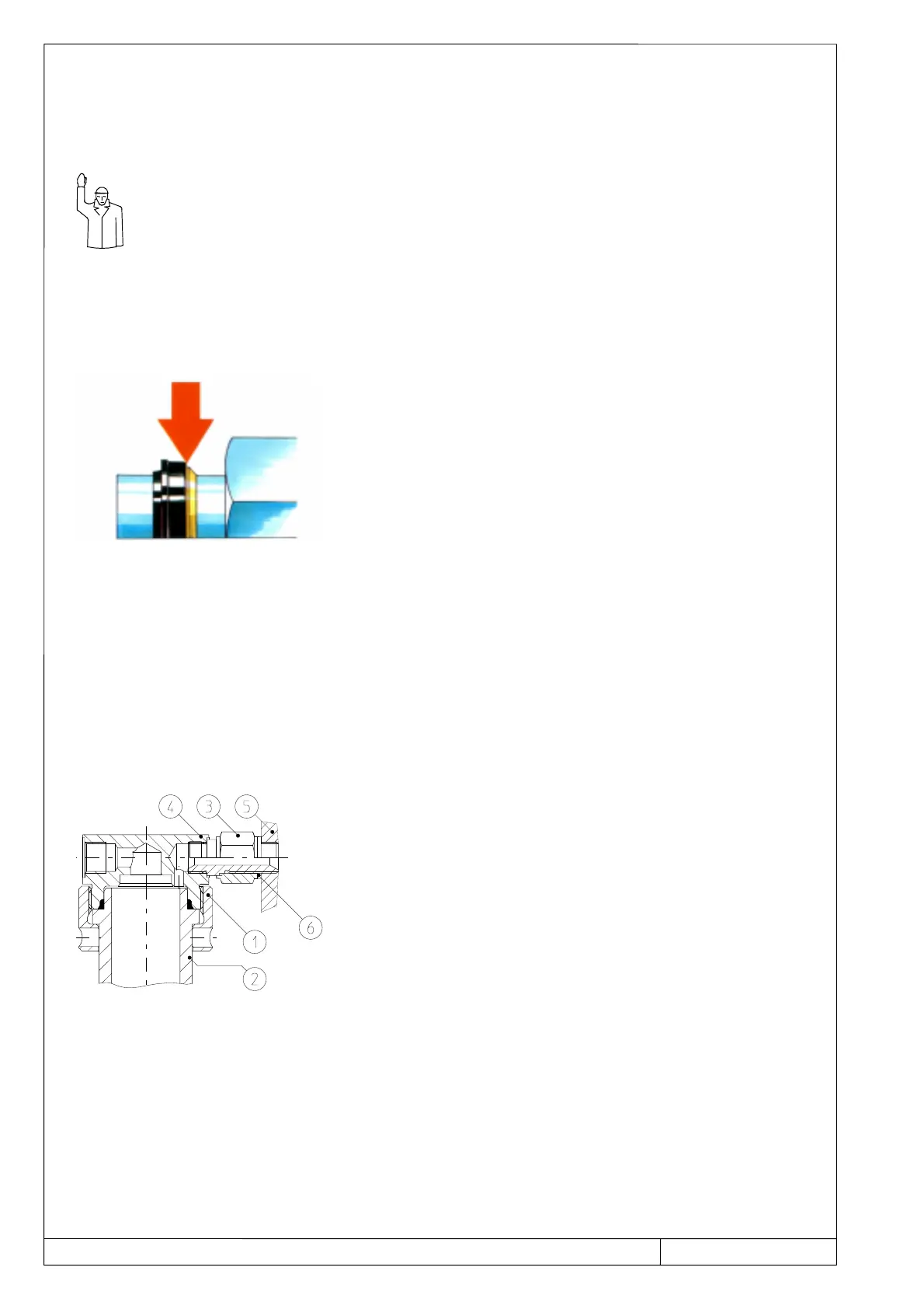
When attaching the suction assembly to the connection 1, pay attention to the following:
Insert the tube end of the suction assembly into the connector and press it against the stop in
the internal taper.
When the end of the tube does not touch the stop, the installation is incorrect.
Continue until clear resistance is felt
– Use the connector as a hold.
Assembly check
Loosen union nut and check whether there is no clearance
between the sealing ring and the retaining ring.
Reassemble after loosening; apply the same torque as the first
time.
Use the connector as a hold.
If the suction assembly has already been fitted to the connector, this unit must be installed first,
e.g. to the wall, before the reciprocating pump is installed.
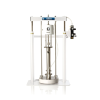
FLUID PRESSURE SYSTEM (SCREEN PN500)
see pages 10 and 11
The Screen PN 500 is usually fitted to the reciprocating pump.
If it is to be retrofitted, the following should be noted:
Screw off the union nut
1 and remove the screen
housing
2.
Pull the nut
3 lightly against the stop of the banjo bolt.
Screw in the connection piece
4 (with banjo bolt and nut)
as far as possible into the reciprocating pump
5.
– Do not forget the sealing ring A 17x21
6.
Tighten the nut
3 against the reciprocating pump (lock).
A connector with G 1/4 or G 3/8 thread is screwed into the screen PN 500 for connecting a hose
line.
– Do not forget the sealing ring A 17x21
6.
The connections for the connector and hose lines have no sealing (sealed head connection) and do
not require any special indications.
– The same applies to the connection of the hose line to a spray gun supplied by us.