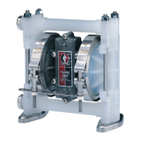
Replacing the Diaphragm Shaft Seals
(See
Fig
5)
1. Remove the screws (35) and washers (36). Gently
tap the air control valve (41) from the top and bot-
tom with
a
plastic mallet to help loosen the air valve
assembly. Then pull the assembly out of the pump
housing.
2.
Disassemble the diaphragm covers and diaphragms
as
instructed in Replacing a Diaphragm,
steps
1-7.
inside the pump housing, and the seals (4) for wear
3. Inspect the shaft (1). the bearings (T-see Detail
B)
are worn, the pump housing must be replaced; the
or damage. Replace parts
as
needed. If the bearings
bearings are not sold separately.
4. Install the new seal (4)
so
the lips of the seal face out
of the pump housing. Press the seal in with your
the seal.
fingers; do not use any tools which could damage
5. Reassemble the diaphragms
as
instructed in
Replacing a Diaphragm, steps 8-18.
6. Look in the pump housing to check the position of
the diephragm shaft (1). Slide the actuator pin (27)
so
that
it
will enter the wmr, housing toward the
small diameter of the shaft toprevent Jamaging the
shaft.
See
Detail
B.
7. Lubricate the outside of the valve caps (30 and
331
with light grease. Guide the air valve assembly into
the pump housing,
so
the arrow on the inlet plate (37)
faces the arrow on the pump housing
(2).
8.
Tap the air inlet plate (37) with
a
plastic mallet to
help align the screw holes of the plate and pump
housing. Install the screw (35) and washer (361 to
check the alignment; adjust
as
necessary. Loosely
install
a
screw and washer in the opposite corner.
Then install the remaining screws and washers. Us-
ing an opposite and alternate pattern, torque the
screws evenly 8.59.5 N.m (6.2-7 ft-lb).
Replacing a Diaphragm (See Fig
5)
1. Remove the pump from
its
mounting.
2.
3.
4.
5.
6.
Remove
the
bolts (14). washers (16) and nuts
(15)
from the outlet manifold
(20).
Tap the manifold with
a
plastic mallet to free
it
from
the pump. Remove
all
four gaskets (17). the valve
seat
plates (18) and the balls (19).
Turn the pump over. Repeat
as
in steps
2
and 3 for
the inlet manifold.
from the diaphragm covers (11) on each side of the
Remove the.bolts (14). washers (16) and nuts (15)
pump.
Hold the shaft bolt
(10)
on one end of the pump and
the pump. Remove the washer (9). fluid side sup-
loosen and remove the bolt (10) on the other end of
port plate
(8).
diaphragm
(7).
air
side support plate
(6) and stop (5).
NOTE:
The diaphragm shaft (1) does not have to be
removed from the pump housing when
replacing
a
diaphragm.
CAUTION
the pump unless the air valve assembly has been
removed. If you do, the actuator pin (27) in the air
7.
Hold the flats on the free end of the diaphragm shaft
with
a
wrench, and loosen the shaft bolt (10).
Remove the plates and diaphragm.
8.
Clean
all
parts thoroughly. Check for wear or
damage and replace parts
as
needed. Lubricate the
parts with light motor oil for easier reassembly.
9. Place
a
stop
(5)
on the shaft
so
the
slots
face into
the pump housing
(2).
Install the air side support
plate (6)
so
the lips face into the
pump
housing. In-
stall the diaphragm (7)
so
the side marked AIR
SIDE
faces the plate (6). Install the fluid side plate
(8)
so
the rounded side faces the diaphragm. Then install
the washer (9) and bolt (101.
See
Detail
C.
10. Install tho diaphragm on the other side of the pump
in
the same way.
11. Align the holes in the diaphragm with the holes in
the flanges of the housing
(2).
Then, without
loos-
ing the alignment, torque the shaft bolts (10) to
42-47 N.m (30-35 ft-lb).
12. Position the diaphragm covers (11) over the
diaphragms
so
the cover arrows
(A)
point upward.
Also align the holes in the diaphragm, housing and
cover.
ICAUT’ON1
you do not
twist
the diaphragm. Twisting the
Be
very careful when installing the cover bolts that
diaphragm prevents
it
from sealing between the
cover and housing and the pump will leak.
13. Loosely install the longer cover
bolts
(3)
and the legs
tom of the cover (11).
(12 and 13). washers (161 and nuts (15) to the bot-
14. Loosely install the bolts (14). with washers and nuts,
15. Using an opposite and alternate pattern, torque the
to the cover (1 1
).
bolts evenly to 13.5-16 N.m (9.8-12 ft-lb).
16.
Be
sure the mating surfaces of the pump housing
17. Working on the inlet side (boaom) first (arrow on
diaphragm covers
will
face down), install
a
gasket
(17).
ball (19). valva seat plate
(18)
and another
gasket (17) on each side of the housing
(2).
and the manifolds are clean.
NOTE:
Be
sure the chamfered side of the valve seat
plate faces the ball.
18.
Install the manifold on the pump housing with the
and the nuts
(15).
Torque the bolts to 27 N.m
bolts (14). a washer.(16) on each end of the bolt,
(20
ft-lb).
19. Turn the pump over. Install a gasket (17). valve seat
plate (18) with chamfer facing the ball, and the ball
(19)
on each side of the housing
(2).
Install the other
gaskets and the outlet manifold
(20)
as in step 18.

 Loading...
