TORQUE TO
6.87.9
Nm
(6-6.8
ft-lb)
23
24
22
TORDUETO
3.44.5
Nm
12.63.3ft-lbJ
APPLY LOCTITE"
NO.
222
TO
THREADS
L41
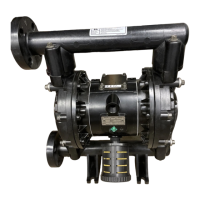
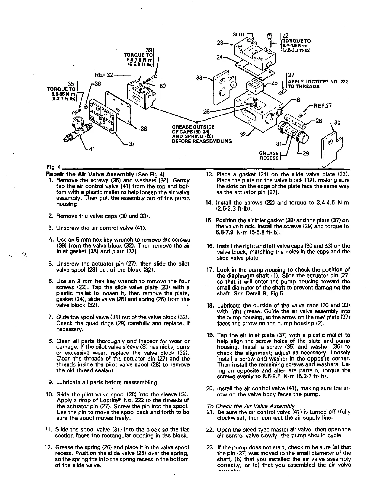
Repair the Air Valve Assembly (See Fig 4)
Fig
4
1.
Remove the screws
(35)
and washers (36). Gently
tap the
air
control valve
(411
from the top and bot-
tom with
a
plastic mallet to help loosen the air valve
assembly. Then pull the assambly out of the pump
housing.
2.
Remove the valve caps
(30
and
33).
3. Unscrew the
air
control valve (41
I.
4.
Use an
5
mm hex key wrench to remove the screws
(39)
from the valve block
(32).
Then remove the air
inlet gasket
(38)
and plate
(37).
..
....
.
:;.
5. Unscrew the actuator pin (271, then slide the pilot
valve spool
(28)
out of the block
(32).
6. Use an 3 mm hex key wrench to remove the four
screws
(221.
Tap the slide valve plate
(23)
with
a
plastic mallet to loosen
it,
then remove the plate,
gasket (241, slide valve (25) and spring (26) from the
valve block
(32).
7. Slide the spool valve (31) out of the valve block
(32).
Check the quad rings
(29)
carefully and replace, if
necessary.
8.
Clean
all
parts thoroughly and inspect for wear or
damage. If the pilot valve sleeve
(SI
has nicks, burrs
or excessive wear, replace the valve block
(321.
threads inside the pilot
valve
spool
(28)
to remove
Clean the threads of the actuator pin 127) and the
the old thread sealant.
9. Lubricate all parts before reassembling.
10. Slide the pilot valve spool
(28)
into the sleeve
(SI.
the actuator pin (271. Screw the pin into the spool.
Apply
a
drop of Loctitem No.
222
to the threads of
sure
the
spool
moves freely.
Use the pin to move the
spool
back and forth to be
11. Slide the spool valve (31) into the block
so
the flat
section faces the rectangular opening in the block.
12. Grease the spring (26) and place
it
in the valve spool
recess. Position the slide valve (25) over the spring,
so
the spring fits into the spring recess in the bonom
of
the slide valve.
13. Place
a
gasket
(24)
on the slide valve plate (23).
the slots on the edge of the plate face the same way
Place the plate on the valve block (32), making sure
as
the actuator pin (27).
14. Install the screws
(22)
and torque to 3.4-4.5 N.m
(2.53.3 ft-lb).
15. Position the air inlet gasket
(381
and the plate
(37)
on
the valve block. Install the screws
(39)
and torque to
6.8-7.9 N.m (55.8 ft-lb).
16. Install the right and left valve caps 130 and 331 on the
valve block, matching the holes in the caps and the
slide valve plate.
17. Look in the pump housing to check the position of
the diaphragm shaft (11.. Slide the actuator pin (271
so
that
it
will enter the pump housing toward the
small diameter of the shaft to prevent damaging the
shaft. See Detail
B,
Fig 5.
18. Lubricate the outside of the valve caps
(30
and
33)
with light grease. Guide the
air
valve assembly into
the pump housing,
so
the arrow
on
the inlet plate
(37)
faces the arrow on the pump housing
(2).
19. Tap the air inlet plate (37) with
a
plastic mallet to
help align the screw ,holes of the plate and pump
housing. Install a screw (35) and washer
(36)
to
check the alignment; adjust as necessary. Loosely
install a screw and washer in the opposite corner.
Then install the remaining screws and washers. Us-
ing an opposite and alternate pattern, torque the
screws evenly to 6.59.5 Nm (6.2-7 ft-lb).
20. Install the air control valve (41
I,
making sure the ar-
row on the valve body faces the pump.
To
Check the Air Valve Assembly
21. Be sure the air control valve (41)
is
turned
Off
(fully
clockwise), then connect the air supply line.
22.
Open the bleed-type master air valve, then open the
air control valve slowly; the pump should cycle.
23. If the pump does not start, check to be sure
(a)
that
the pin (27) was moved to the small diameter
of
the
shaft, (b) that you installed the air valve assembly
correctly, or (cl that you assembled the air valve
"."..*,..