Installation
6 3A2099D
Grounding
Installation Procedure
NOTE: Reference letters used in the following instruc-
tions refer to Parts page 10 or Component Identification,
page 5.
The lubricator should be solidly mounted and aligned to
connect the drive shaft to the proper stroking or rotary
motion. This drive motion, through the lubricator drive,
should operate the lubricator drive shaft and hand crank
shaft between 3 and 60 RPM. There is one pump stroke
for every revolution of the hand crank shaft, which is an
extension of the drive shaft shaft.
1. Select a mounting surface that will satisfy the follow-
ing goals:
• Is able to support the weight of the reservoir
and fluid when filled to capacity.
NOTE: When possible, mount to a surface that
experiences little or no vibration.
• Allows easy access to the lubricator for filling
the reservoir and periodic maintenance.
• The lubricator must be grounded through the
mounting bolts.
2. Install reservoir (L) to the mounting surface. Use the
mounting diagram (page 13) to determine location
to drill mounting holes.
3. Install bolts through reservoir and mounting holes
and tighten securely.
4. Install protective guards around all drive compo-
nents.
5. Remove fill cap (A) and fill reservoir with new or
clean, filtered fluid until it reaches the top of the res-
ervoir gauge glass.
Start Up
NOTE: Reference letters used in the following instruc-
tions refer to Component Identification, page 5.
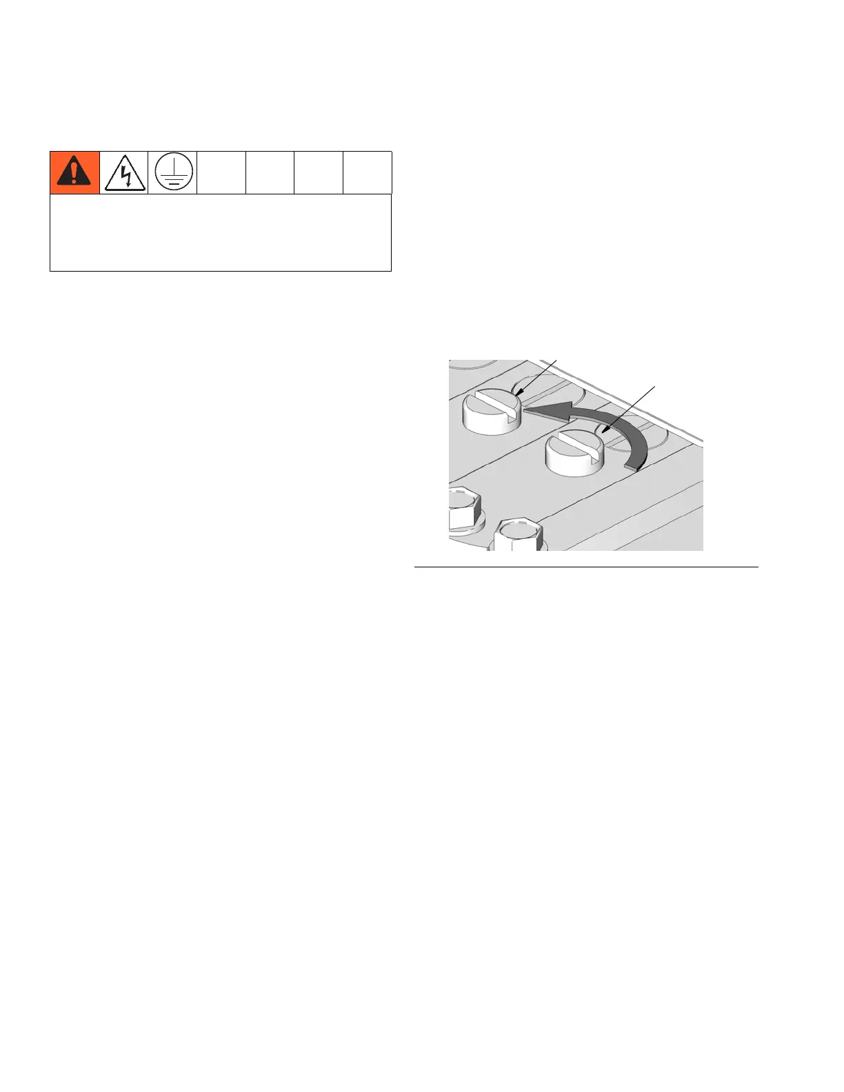
1. For initial start-up, prime the pump by removing
screw from outlet metering circuit (S) (F
IG. 2) and
filling the small chamber with oil. Reattach the
screw, making sure the spring lines up vertically.
2. Adjust the pump for maximum delivery by turning
the feed regulator (C) counter- clockwise as indi-
cated by the directional arrow (F
IG. 2).
3. Operate pumps at this setting and bleed lubrication
lines at the terminal check valve to assure full lubri-
cation.
Feed Rate Regulation
The proper drive shaft shaft RPM is determined from the
required maximum and minimum pump feed rates.
Each pumping unit is regulated independently by means
of the feed regulator (C). When a pump is correctly set
to its required feed rate, the feed rate can still be
increased or decreased by the feed regulator (C). In
most cases due to the wide adjustment range of the
pump units, there will be considerable allowance in the
selection of the proper drive shaft speed.
• Turn the feed regulator (C) clockwise to DECREASE
the feed.
• Turn the feed regulator (C) counter-clockwise to
INCREASE the feed.
The equipment must be grounded. Grounding
reduces the risk of static and electric shock by
providing an escape wire for the electrical current due
to static build up or in the event of a short circuit.
FIG. 2