Installation
Installation
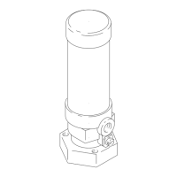
1. Connect the component A supply to the A side
fitting (19a) of the mix manifold.
2. Connect the component B supply to the B side
fitting (19b) of the mix manifold.
3. Connect the solvent supply to the solvent fitting
(20) of the mix manifold.
4. Connect the static mixer hose (106) to the gun
whip hose.
This equipment must be grounded to reduce
the risk of static sparking. Static sparking can
cause fumes to ignite or explode. Grounding
provides an escape wire for the electric current.
5. Connect the ground wire (105) to the ground
screw (23). Connect the other end of the ground
wire to a true earth ground.
F
igure 1 Mix Manifold
Operation
1. Check that all
hose connections are tight before
each use.
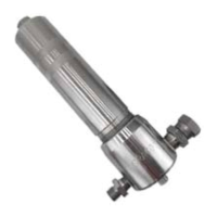
2. To spray, move
the lever (16) to the
(SPRAY) posi
tion. Components A and B will
enter the mix
manifold and be mixed by the mix
nozzle (10) a
nd the static mixer tube (106).
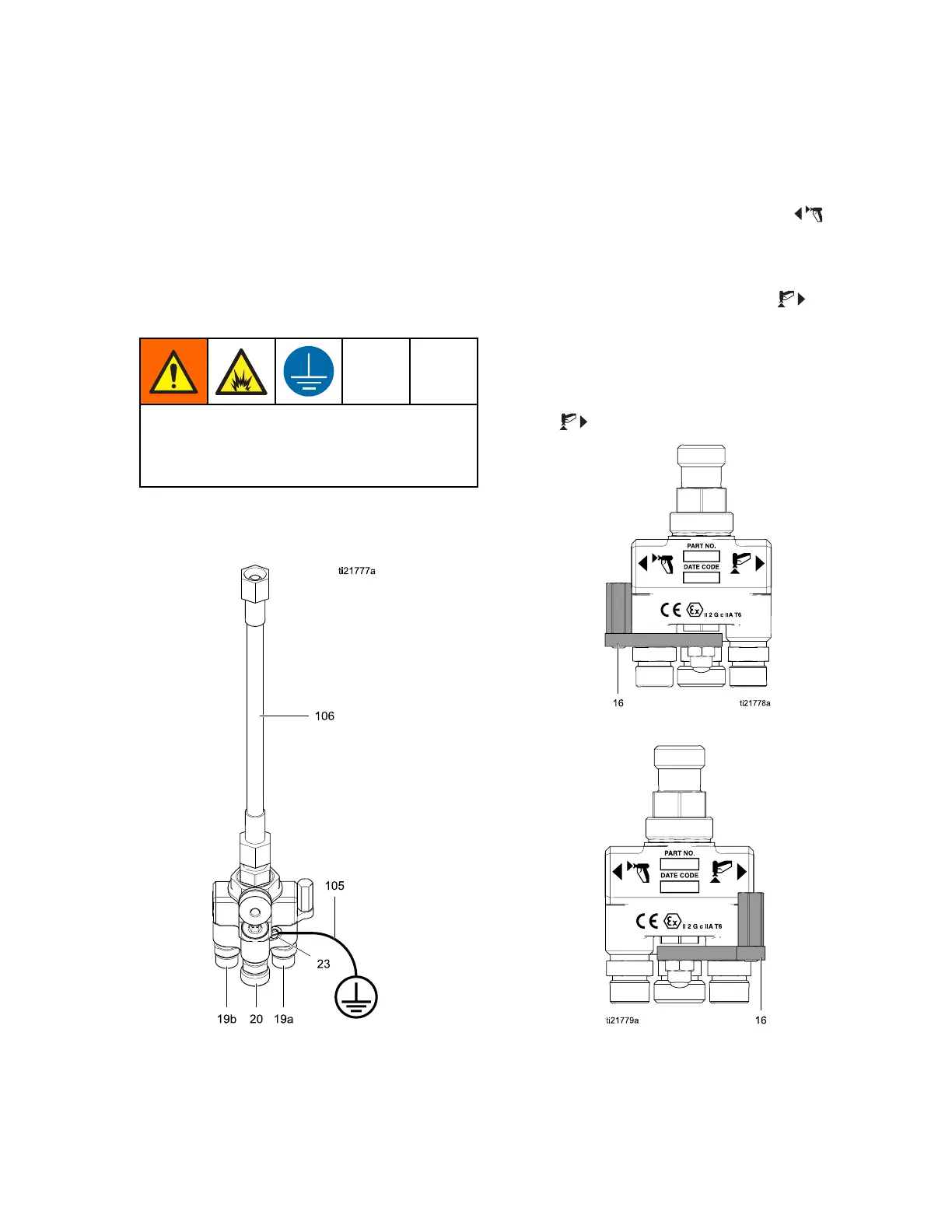
3. To flush, mov
e the lever (16) to the
(FLUSH)
position. S
olvent will flush the mix manifold,
static mixe
r, and gun.
4. To shut dow
n, flush the mix manifold and relieve
pressure a
s described in the PD2K operation
manual. Al
ways leave the mix manifold lever in
the
(FLUSH
) position when not in use.
Figure 2 Mix Manifold Set to Spray
Fi
gure 3 Mix Manifold Set to Flush
3A2801A 5